Structure and method for self-aligning rotor blade joints

a technology of rotor blades and joints, which is applied in the direction of machines/engines, transportation and packaging, and final product manufacturing, etc., can solve the problems of long road transportation, limited routing of trucks, and high cost of single-piece rotor blades, and achieve the effect of facilitating mating

Active Publication Date: 2010-12-09
GENERAL ELECTRIC CO
View PDF4 Cites 68 Cited by
  • Summary
  • Abstract
  • Description
  • Claims
  • Application Information

AI Technical Summary

Benefits of technology

[0007]Briefly in accordance with one aspect of the present invention, an alignment structure for precision alignment and clamping of sections of a multi-section wind turbine blade is provided. A plurality of blade sections form joints between adjacent blade sections, including at least a first section and a second section.
[0008]A bulkhead is mounted on the inner surface of a shell of the first section at an outer end. A bulkhead is mounted on the inner surface of a shell of the second section at an inner end. One or both of these bulkheads may include a plurality of male alignment pins in predetermined locations on an exterior surface and extending normal to an exterior surface of the opposite bulkhead. One or both of these bulkheads may include a plurality of bushings in predetermined complimentary locations for receiving the plurality of male alignment pin of the opposite bulkhead. The associated male alignment pins and the bushings are precisely aligned on the exterior end surfaces of the bulkheads to facilitate mating of the first section and the second section. Both the bulkhead for the first section and the second section also include corresponding aligned through holes. When adjacent blade sections have been fully, or nearly fully engaged, the through holes may be provided with nuts and bolts or other known fastening devices to clamp the bulkheads together and thereby join the first section and second section together. With the first section and the second section clamped together in this manner, the unified blade is provided with adequate support for hoisting or movement, until the joint is permanently secured.

Problems solved by technology

The large blade size may severely limit the maneuverability of the trucks.
Road transport of long, single-piece rotor blades is also very costly.
Furthermore, routing of the trucks may be limited since it may be impossible to negotiate sharp turns and other interferences.
Extraordinary blade length may also make loading and unloading extremely difficult.
While individual sections of the multi-section blades are smaller than a one-piece blade, they are still long and heavy.
With long and heavy blade sections, the fine alignment of the individual blade sections at the joints poses difficulty, particularly under conditions of nature that may be present at the destination windfarm sites.

Method used


Image

  • Structure and method for self-aligning rotor blade joints
  • Structure and method for self-aligning rotor blade joints
  • Structure and method for self-aligning rotor blade joints

Examples


Embodiment Construction

[0028]The following embodiments of the present invention have many advantages, including providing a structure and method for precision alignment of joints between adjacent sections of a wind turbine blade.

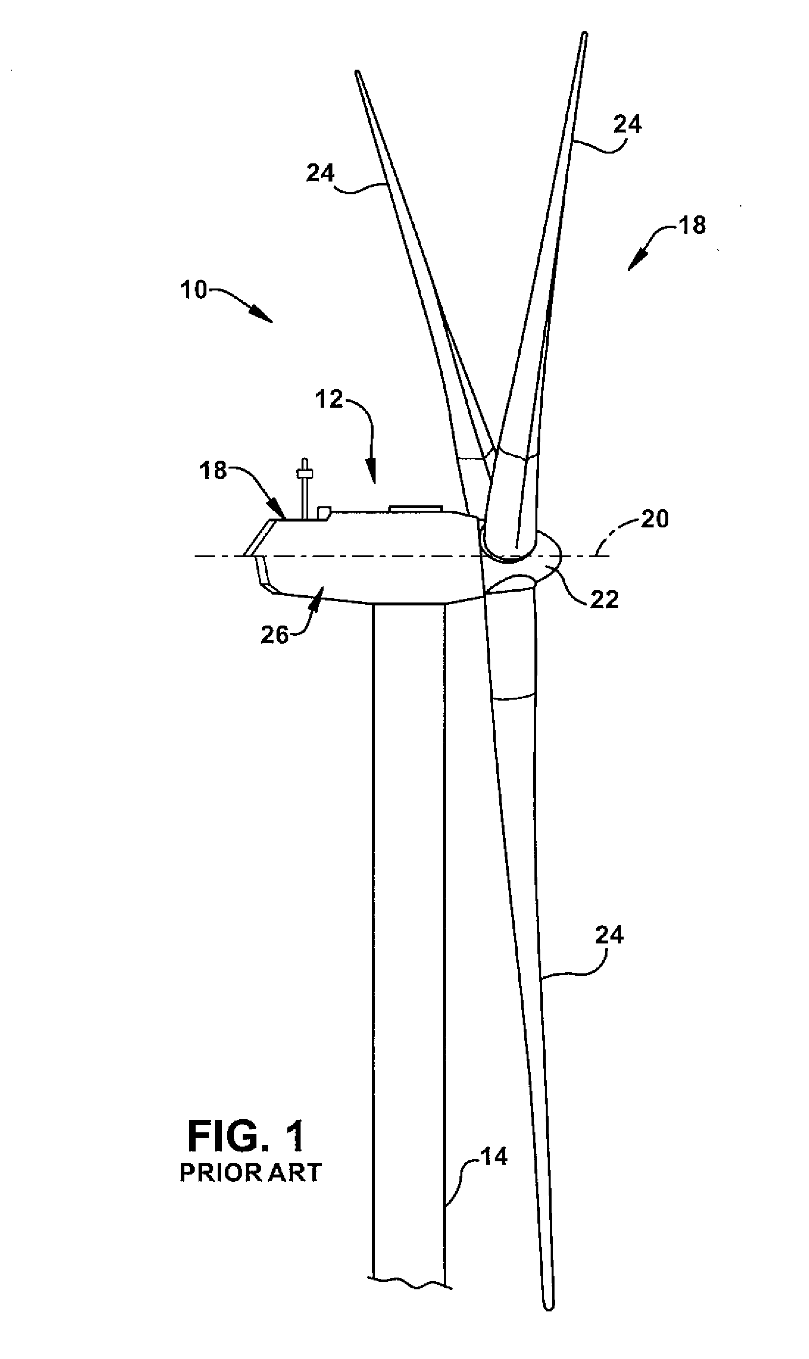
[0029]FIG. 1 is a schematic illustration of an exemplary wind turbine 10. In the exemplary embodiment, wind turbine 10 is a horizontal axis wind turbine. Wind turbine 10 includes a tower 14, a nacelle 16 coupled to tower 14, and a rotor 18 coupled to nacelle 16 for rotation about an axis of rotation 20. Rotor 18 includes a rotatable hub 22 and a plurality of rotor blades (“blades”) 24 coupled to hub 22. In the exemplary embodiment, rotor 18 includes three blades 24. In an alternative embodiment, rotor 18 may include more or less than three blades 24. General operation, dimensions, and configuration of wind turbine 10, and more specifically wind generator 12, is known in the art and therefore will not be described in more detail herein.

[0030]Normally the body sections of the multi-...


PUM

PropertyMeasurementUnit
lengthsaaaaaaaaaa
distanceaaaaaaaaaa
physical separationaaaaaaaaaa

Abstract

An inventive self-aligning blade joint structure is provided to facilitate assembly and clamping of wind turbine blade sections carried on a transporter. The blade joint structure includes alignment pins on one end bulkhead of a blade body section at the joint and complimentary female bushings on a bulkhead of an adjacent blade body section to permit fine alignment of the joint. The blade joint structure also includes through holes in the end bulkheads for the adjacent blade body sections to permit clamping of the sections in preparation for application of adhesive bonding to the joint. A pair of male scarfed surfaces of spar caps extend from one blade section into the second blade section and engage female scarfed surfaces of spar caps formed in the second blade section and recessed from the joint. An inventive method is provided to utilize the self-aligning blade joint structure for assembly of the blade sections.

Description

BACKGROUND OF THE INVENTION[0001]The invention relates generally to assembling sections of wind turbine blades and more specifically to an alignment and clamping structure and method for assembling multi-sectional wind turbine blades.[0002]In recent years, wind turbines have become increasingly important in power generation. With increased environmental concerns related to fossil fuel power generation, wind power will grow in importance in the mix of providing electrical power. Consequently, more wind turbines will be installed. For economic reasons, it is desirable to increase the installed power per turbine. As the installed power is proportional to the diameter of the turbine rotor, the rotor sizes and turbine sizes become larger. Blade lengths continue to increase to support the higher power requirements per turbine. Typical blade lengths of current designs are up to 50 meters and greater.[0003]Due to the often-isolated location of wind turbine farms, the rotor blades must be tr...

Claims


Application Information

Patent Timeline
Patent Type & Authority Applications(United States)
IPC IPC(8): F03D11/00B23P15/04
CPCF03D1/001F03D1/0675F05B2230/60Y10T29/49337Y02E10/721Y02E10/728F05B2240/302F03D13/10Y02E10/72Y02P70/50
Inventor LIVINGSTON, JAMIE T.
Owner GENERAL ELECTRIC CO
Why Eureka
Try Eureka