Apparatus and Method of Applying a Coating Solution

a technology of coating solution and apparatus, applied in the direction of coatings, liquid spraying apparatus, movable spraying apparatus, etc., can solve the problems of loss of coating solution, uneven coating, step or unevenness at the boundary, etc., and achieve the effect of increasing the time required for coating the entire surface area of the glass plate and complicated control of the nozzl

Inactive Publication Date: 2010-12-09
CENT GLASS CO LTD
View PDF8 Cites 21 Cited by
  • Summary
  • Abstract
  • Description
  • Claims
  • Application Information

AI Technical Summary

Benefits of technology

[0019]In the conventional art described in the Patent Literature 2, the elongated brush having a width larger than a length of one side of the curved window glass of an automobile is immersed in the liquid chemical and moved upward and downward along a shape of a curving surface of the plate-like article between one end and the opposite end of the plate-like article so as to be reciprocated by at least one stroke and thereby uniformly apply the liquid chemical to the surface of the plate-like article. Therefore, the conventional art described in the Patent Literature 2 is improved so as to reduce the above-described problems in the conventional art described in the Patent Literature 1. However, in a case where a quick drying liquid chemical is applied to a glass plate having such a size as that of a window glass of an automobile, much application time is needed to apply the liquid chemical to an entire surface of the glass plate, and therefore, the liquid chemical on an already coated portion of the surface of the glass plate is solidified and crystallized before finishing coating of the entire surface of the glass plate. There occurs a step or unevenness at a boundary between the already coated portion of the surface of the glass plate and a non-coated portion thereof before subjecting to coating.
[0021]Further, in the conventional method of spraying the coating solution through nozzles as described in the Patent Literature 4, an upper peripheral side of the film-forming surface of the glass plate is supported in a suspended state, and a plurality of nozzles are moved from one vertical side of the glass plate toward the opposite vertical side thereof while spraying the coating solution from the nozzles. Since the coating solution is applied to the surface of the glass plate is flowed downwardly along the surface of the glass plate, the surface coated with the coating solution by the lower-side nozzle is further coated with the coating solution by the upper-side nozzle so that production of a coat having a uniform thickness is prevented due to the overlapped application of the coating solution.
[0025]A first object of the present invention is to solve the above problems in the conventional arts and provide a simply constructed apparatus and a method of uniformly applying a necessary minimum amount of a quick drying coating solution to only an upper surface of a curved glass plate having a concaved central portion of the upper surface at high speed without causing unevenness.
[0026]A second object of the present invention is to solve the above problems in the conventional arts and provide a simply constructed apparatus and a method of applying a necessary minimum amount of a coating solution that tends to absorb a moisture in the air to an upper surface of a rectangular flat plate-like article such as a glass plate and a resin panel with a coating efficiency of 100% without circulating the coating solution, to thereby form a uniform coat on the upper surface of the plate-like article without causing wraparound of the coating solution to an underside of the plate-like article.

Problems solved by technology

Therefore, in a case where the coating material is applied to an entire surface of the glass plate with the brush, there will occur a step or unevenness at a boundary between an already coated portion of the glass plate surface and a non-coated portion thereof before subjecting to application of the coating material.
Further, since a long application time is needed in order to apply the coating material to the entire surface of the glass plate with the brush, the coating solution in the brush is solidified which inevitably results in occurrence of unevenness in coating.
Further, in the conventional method of showering the coating solution as described in the Patent Literature 3, there occurs a loss of the coating solution due to increase in splashing off the coating solution outside of the surface of the glass plate, and it tends to cause wraparound of the coating solution to the underside of the glass plate.
In particular, in a case where the coating solution to be showered is a quick drying coating solution, the coating solution is partially crystallized to cause unevenness in coating thickness as the coating solution is dried.

Method used


Image

  • Apparatus and Method of Applying a Coating Solution
  • Apparatus and Method of Applying a Coating Solution
  • Apparatus and Method of Applying a Coating Solution

Examples


example 1

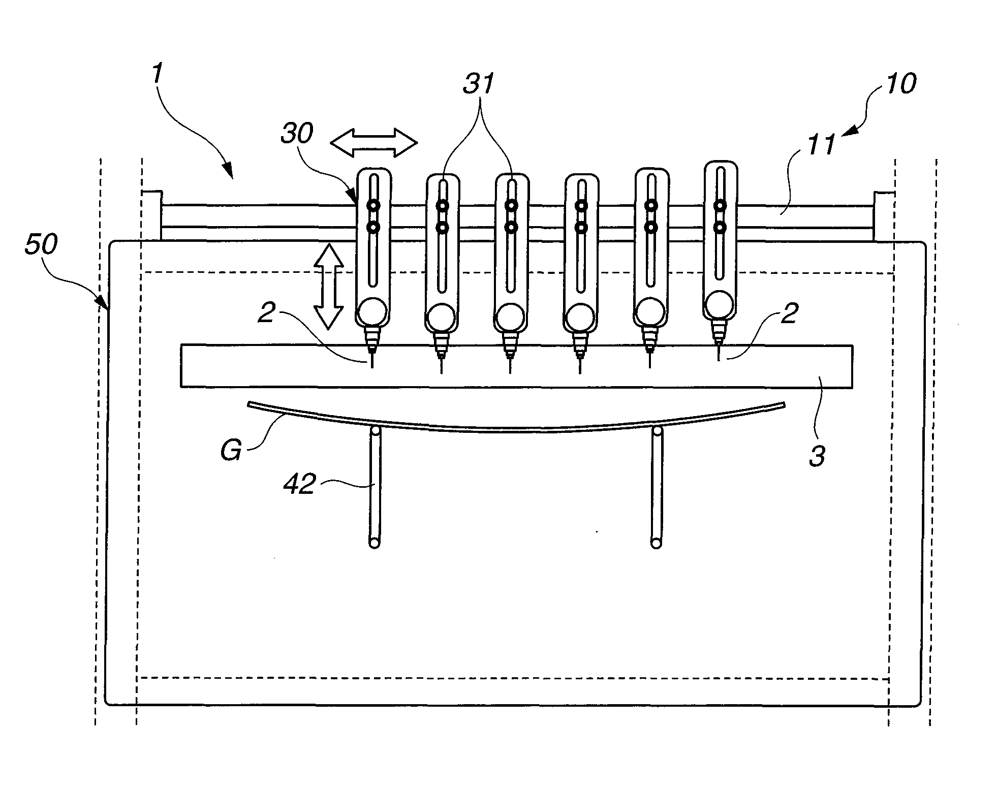
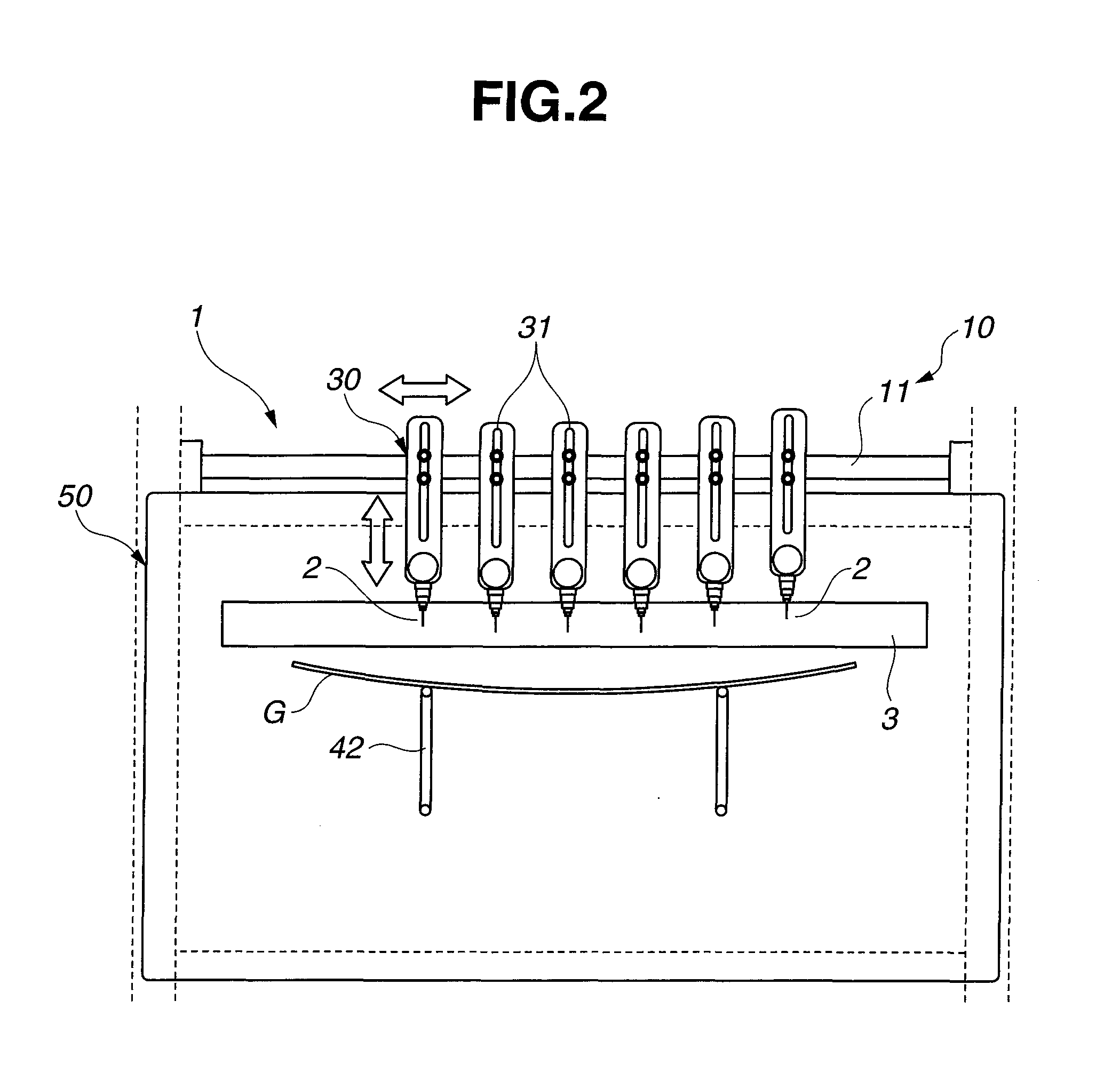
[0119]As shown in FIG. 2 to FIG. 4, the respective positions of a plurality of coating nozzles in a width direction (i.e., a horizontal direction) of the glass plate G are previously adjusted by the nozzle position adjuster 10 according to a shape of a surface of the glass plate G.

[0120]As shown in FIG. 2, the heights of the respective coating nozzles are previously adjusted along the curved surface of glass plate G in the width direction thereof.

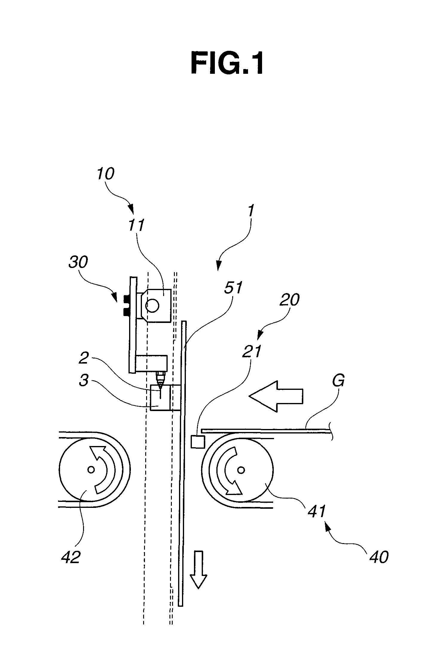
[0121]As shown in FIG. 1 and FIG. 2, when the glass plate G is transported to the vicinity of the ascent / descent door 51 by the supply conveyer 41 in order to successively introduce the glass plate G into the coating chamber 50, the distal leading edge of the glass plate G is detected by the glass plate G detecting sensor 21 and the ascent / descent door 51 at an inlet of the coating chamber 50 is downwardly moved to an opened state thereof.

[0122]When the ascent / descent door 51 is downwardly moved, the solvent tank mounted to a wall surface o...

example 2

[0131]As shown in FIG. 6 and FIG. 7, corresponding to the width of the glass plate G held in the predetermined position in the previous step, the mounting positions of the nozzles 111, 111, . . . are adjusted by the fitting members (not shown) therefor which are mounted to the slidably movable guides 32. The guides 32 are so disposed as to slidably move on the rail 131 that is provided in the width direction of the glass plate G (i.e., in the horizontal direction). Further, the plurality of nozzles 111, 111, . . . are selectively used according to the data stored per kind of glass plate G in the controller.

[0132]Furthermore, in a case where it is required to adjust the height position of each of the nozzles Mowing to variation in thickness of the glass plate G or the like, the position of each of the nozzles 111 can be adjusted in the height direction, namely, in the up-and-down direction by allowing the nozzle to move along a vertical elongated hole formed in the respective fitting...

example 3

[0141]As shown in FIG. 8, there were provided two rails 131 for supporting the coating nozzles. The plurality of nozzles 111 were alternately arranged on the two rails 131, 131 in the width direction of the glass plate G so as to form a zigzag pattern. In this case, the timings of starting application of the coating solution by the respective nozzles 111, 111, . . . were set so as to apply the coating solution from predetermined coating positions on the upper surface of the glass plate which are located on a side of the leading edge of the glass plate, by correcting the distance between each of the nozzles and the sensor 141.

[0142]With this arrangement of the nozzles, the nozzles could be disposed with intervals therebetween which are smaller than a width of the respective electromagnetic valves.


PUM

PropertyMeasurementUnit
lengthaaaaaaaaaa
lengthaaaaaaaaaa
diameteraaaaaaaaaa

Abstract

A method of applying a coating solution onto an upper surface of a glass plate that is transported in a substantially horizontal attitude, according to the first aspect of the present invention, the method including the steps of transporting the glass plate into a coating chamber, and opening the plurality of coating nozzles which are positioned in a row at constant intervals therebetween along a curved shape of the upper surface of the glass plate in a width direction of the glass plate perpendicular to the direction of transporting the glass plate by the nozzle position adjusting means and the nozzle height adjusting means, to thereby inject the coating solution when the coating nozzles are located in a region of the upper surface of the glass plate which extends from the leading edge of the glass plate to the rear edge of the glass plate.

Description

TECHNICAL FIELD[0001]The present invention relates to an apparatus and a method of applying a coating solution onto a surface of a plate-like article such as a glass plate and a resin panel. More particularly, the present invention relates to an apparatus and a method of applying a quick drying coating solution, for instance, a film forming liquid which is used for forming an infrared ray (IR) cutting film by applying a silica binder containing indium tin oxide (ITO), etc., onto a curved profile surface of a glass plate such as a window glass of automobiles.[0002]In addition, the present invention relates to an apparatus for uniformly applying a minimum amount of a coating solution onto a surface of a plate-like article such as a glass plate and a resin panel without causing wraparound of the coating solution to a rear surface of the article. More particularly, the present invention relates to an apparatus for applying a coating solution which is useful to uniformly form a film to b...

Claims


Application Information

Patent Timeline
Patent Type & Authority Applications(United States)
IPC IPC(8): B05D1/02B05C11/02B05C5/00
CPCB05B12/04B05B12/122C03C17/002B05B13/0278B05B15/025B05B13/0221B05B15/55B05B15/68
Inventor SHIOI, TAKAFUMINAKANO, TADAAKIHAMAGUCHI, SHIGEOAKAMATSU, YOSHINORIITAKURA, NOBUYUKI
Owner CENT GLASS CO LTD
Why Eureka
Try Eureka