Method of manufacturing piezoelectric vibrator, piezoelectric vibrator, oscillator, electronic device, and radio clock

a manufacturing method and technology of piezoelectric vibrators, applied in the direction of generators/motors, piezoelectric/electrostrictive transducers, transducer types, etc., can solve the problems of inability to seal the through hole, inability to secure the air tightness in the cavity c, and melting of the through electrode 205/b>, so as to improve the quality of the oscillator and ensure the air tightness in the cavity. , the effect o

Inactive Publication Date: 2010-12-16
SII CRYSTAL TECH
View PDF3 Cites 5 Cited by
  • Summary
  • Abstract
  • Description
  • Claims
  • Application Information

AI Technical Summary

Benefits of technology

[0019]In particular, a member made of a material in which ions can be transferred at a bonding temperature is used as the dummy member. Accordingly, by heating up to a bonding temperature and applying a driving voltage between the electrode plate and the bonding film by a heating process and the applying process, the transfer of ions (charged particles) locally occurs in the base substrate wafer and the dummy member, which are interposed between the electrode plate and the bonding film. As a result, current flows in the base substrate wafer and the dummy member. In contrast, the bonding film does not come into contact with the through electrodes and the through electrodes are not interposed between the bonding film and the electrode plate. Accordingly, even though a voltage is applied between the bonding film and the electrode plate, the transfer of ions does not occur. In addition, since the dummy member is interposed between the through electrodes and the electrode plate, current does not directly flow from the electrode plate to the through electrodes. That is, even though a bonding voltage is applied between the bonding film and the electrode plate in the applying process, current does not flow in the through electrodes and a potential difference as high as the bonding voltage cannot be generated between the bonding film and the through electrodes. For this reason, it may be possible to suppress the occurrence of electric discharge (spark discharge) that has frequently occurred in the related art between the bonding film and the through electrodes.
[0034]Further, since the oscillator, the electronic device, and the radio clock each include the above-mentioned piezoelectric vibrator, likewise, it may also be possible to improve the quality of the oscillator, the electronic device, and the radio clock.

Problems solved by technology

As a result, there has been a problem in that the through electrode 205 having been subjected to electric discharge is melted.
In addition, if the through electrode 205 is melted, it may not be possible to seal the through hole 204.
For this reason, there also has been a possibility that airtightness in the cavity C cannot be secured.
Therefore, it was not possible to reliably seal both the substrates, and it also was difficult to secure airtightness in the cavity C.

Method used


Image

  • Method of manufacturing piezoelectric vibrator, piezoelectric vibrator, oscillator, electronic device, and radio clock
  • Method of manufacturing piezoelectric vibrator, piezoelectric vibrator, oscillator, electronic device, and radio clock
  • Method of manufacturing piezoelectric vibrator, piezoelectric vibrator, oscillator, electronic device, and radio clock

Examples


Embodiment Construction

[0055]An embodiment of the invention will be described below with reference to FIGS. 1 to 14.

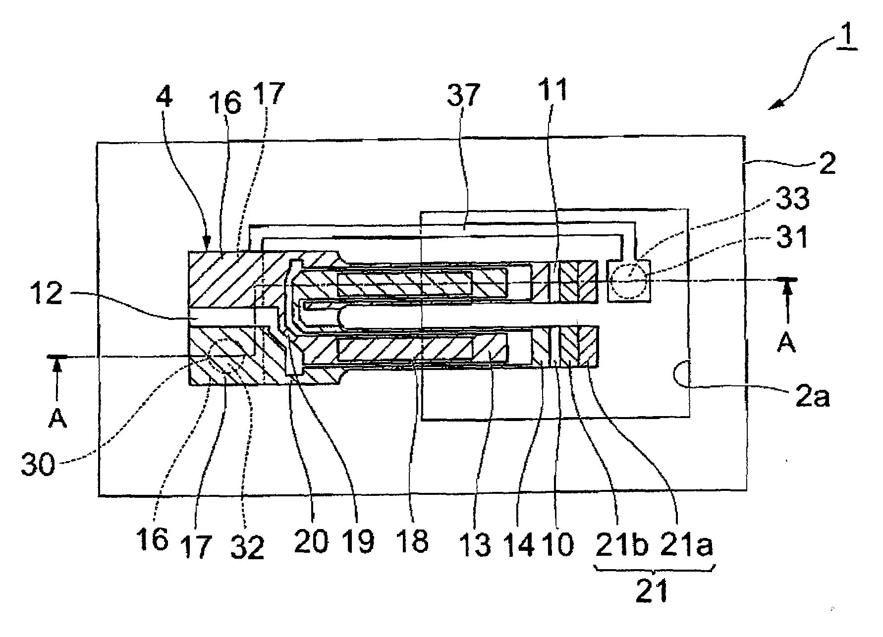
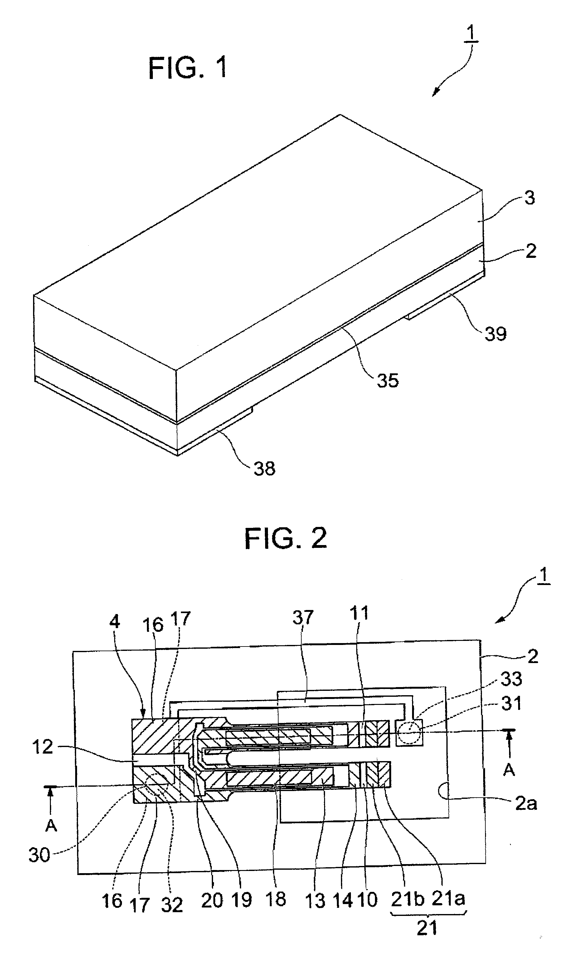
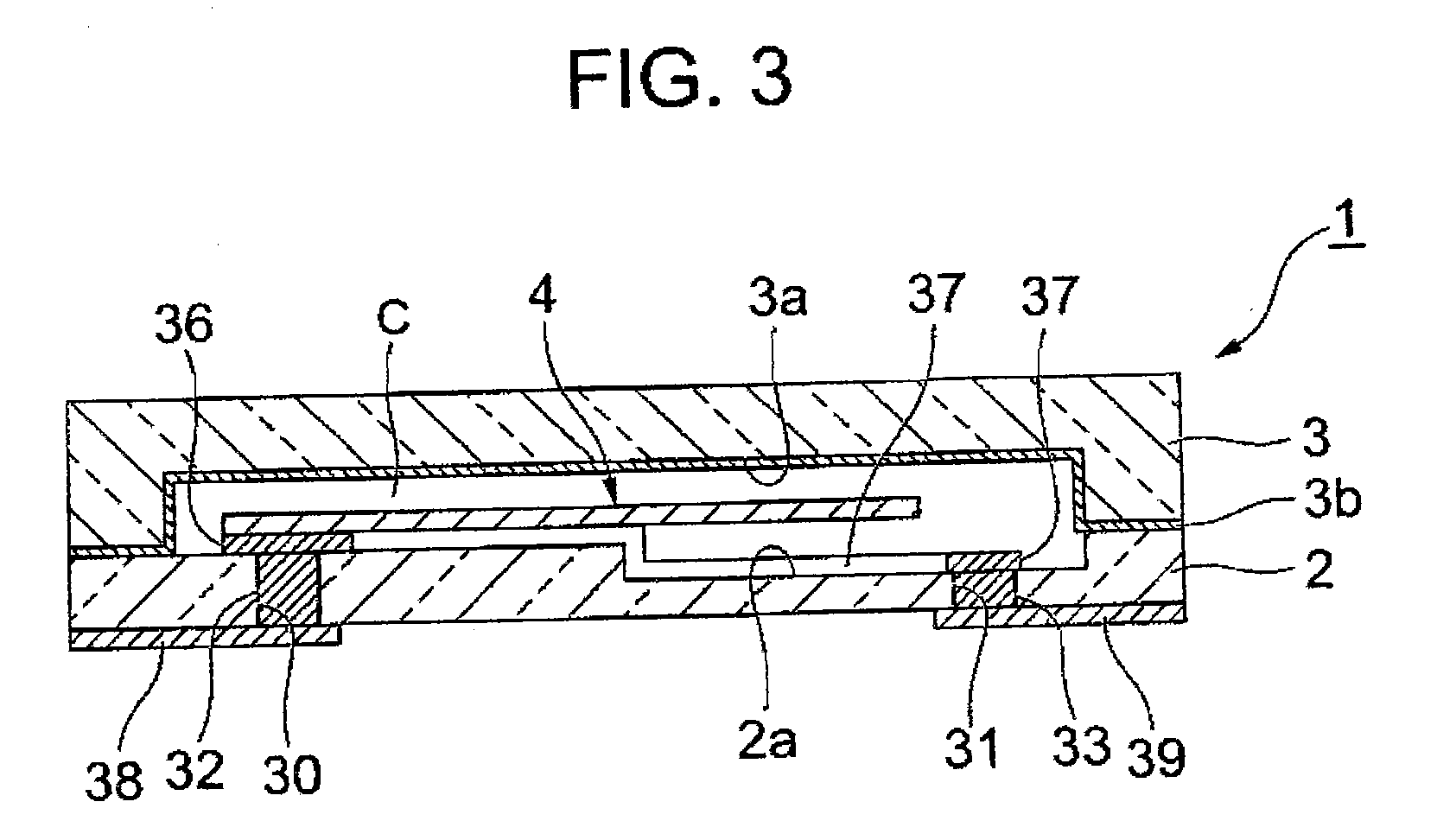
[0056]As shown in FIGS. 1 to 4, a piezoelectric vibrator 1 according to this embodiment is formed in a box shape where two layers (a base substrate 2 and a lid substrate 3) are laminated, and is a surface mounted piezoelectric vibrator 1 where a piezoelectric vibrating reed 4 is received in an inner cavity C.

[0057]Meanwhile, for the easy understanding of drawings, an excitation electrode 15, extraction electrodes 19 and 20, mount electrodes 16 and 17, and a weight metal film 21, which are to be described below, are not shown in FIG. 4.

[0058]As shown in FIGS. 5 to 7, the piezoelectric vibrating reed 4 is a tuning-fork type vibrating reed that is made of a piezoelectric material, such as crystal, lithium tantalite, or lithium niobate. When a predetermined voltage is applied to the piezoelectric vibrating reed, the piezoelectric vibrating reed vibrates.

[0059]The piezoelectric vibrating reed 4 i...


PUM

PropertyMeasurementUnit
temperatureaaaaaaaaaa
bonding temperatureaaaaaaaaaa
voltageaaaaaaaaaa

Abstract

When a base substrate where through electrodes are formed is anodically bonded to a lid substrate that includes a bonding film formed on the entire lower surface thereof, a method of manufacturing a piezoelectric vibrator includes a superimposing process for superimposing the lid substrate on the base substrate so that a piezoelectric vibrating reed is received in a cavity, after bonding the piezoelectric vibrating reed to the upper surface of the base substrate; a setting process for placing a dummy member, which is made of a material in which ions can be transferred at a bonding temperature, on an electrode plate, and placing the superimposed substrates on the dummy member so that the base substrate faces the dummy member; and an applying process for applying a bonding voltage between the electrode plate and the bonding film after heating the dummy member and the substrates up to the bonding temperature.

Description

RELATED APPLICATIONS[0001]This application is a continuation of PCT / JP2008 / 072622 filed on Dec. 12, 2008, which claims priority to Japanese Application No. 2008-039860 filed on Feb. 21, 2008. The entire contents of these applications are incorporated herein by reference.BACKGROUND OF THE INVENTION[0002]1. Field of the Invention[0003]The present invention relates to a method of manufacturing a surface mounted (SMD) piezoelectric vibrator where a piezoelectric vibrating reed is sealed in a cavity formed between two bonded substrates, a piezoelectric vibrator manufactured by the method, and an oscillator, an electronic device, and a radio clock that each include the piezoelectric vibrator.[0004]2. Description of the Related Art[0005]In recent years, a piezoelectric vibrator, which employs crystal or the like as a time source, a timing source of a control signal or the like, a reference signal source or the like, has been used in a cell phone or a portable information terminal device. V...

Claims


Application Information

Patent Timeline
Patent Type & Authority Applications(United States)
IPC IPC(8): H01L41/22H01L23/02H03B5/32H03H3/02H03H9/02
CPCH03H3/02H03H9/0542H03H9/1021H03H9/21H03H2003/026Y10T29/42
Inventor ARATAKE, KIYOSHIKAWADA, YASUO
Owner SII CRYSTAL TECH
Why Eureka
Try Eureka