
Weld defect detection systems and methods for laser hybrid welding

a laser hybrid welding and defect detection technology, applied in the direction of soldering equipment, manufacturing tools, auxilary welding devices, etc., can solve the problems of reducing or eliminating the applicability of laser hybrid welding, the inability to accept gaps in joints, and the challenge of laser hybrid welding surrounding gap filling

Active Publication Date: 2010-12-16
ILLINOIS TOOL WORKS INC
View PDF12 Cites 144 Cited by
  • Summary
  • Abstract
  • Description
  • Claims
  • Application Information

AI Technical Summary

Benefits of technology

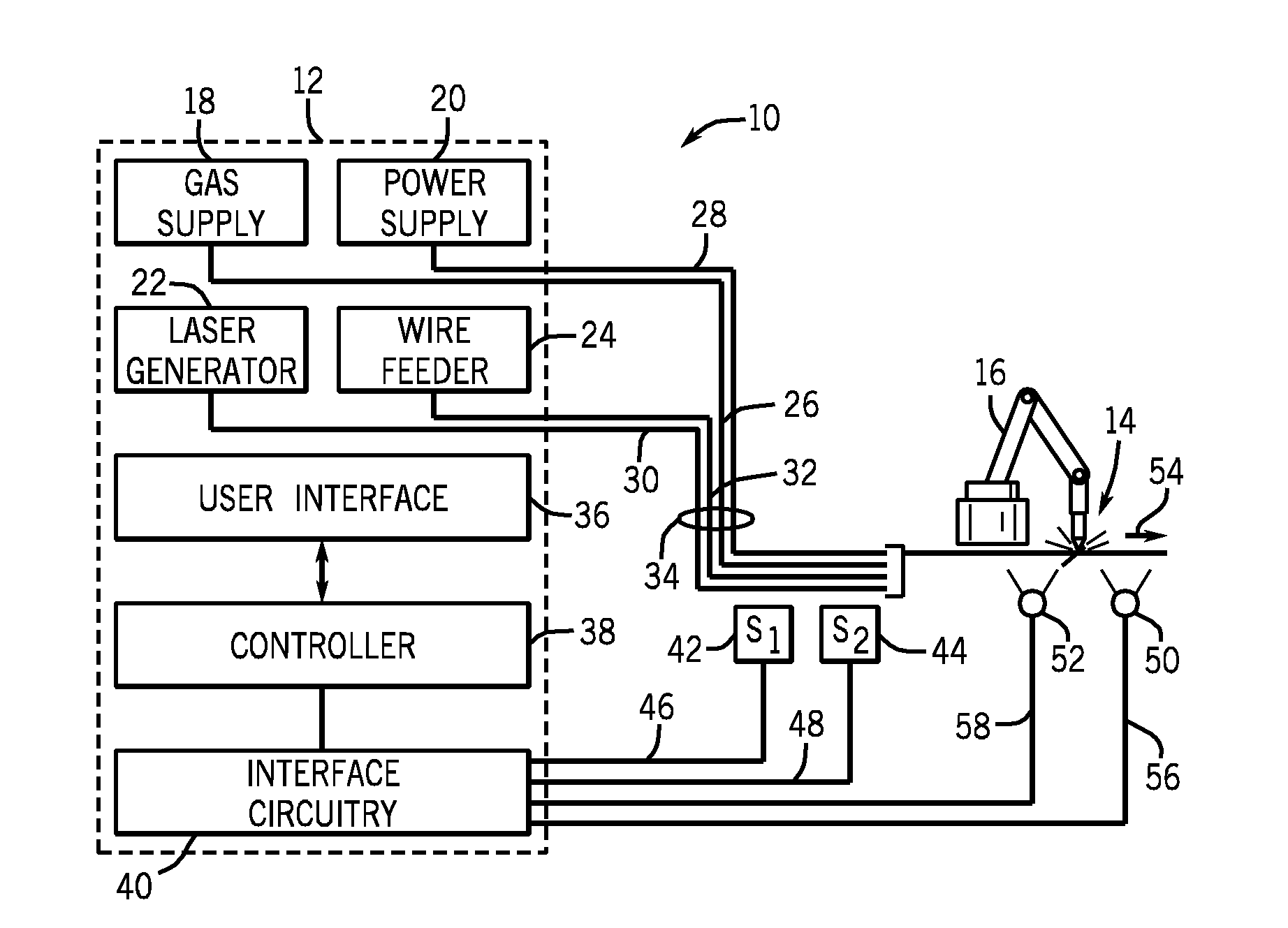
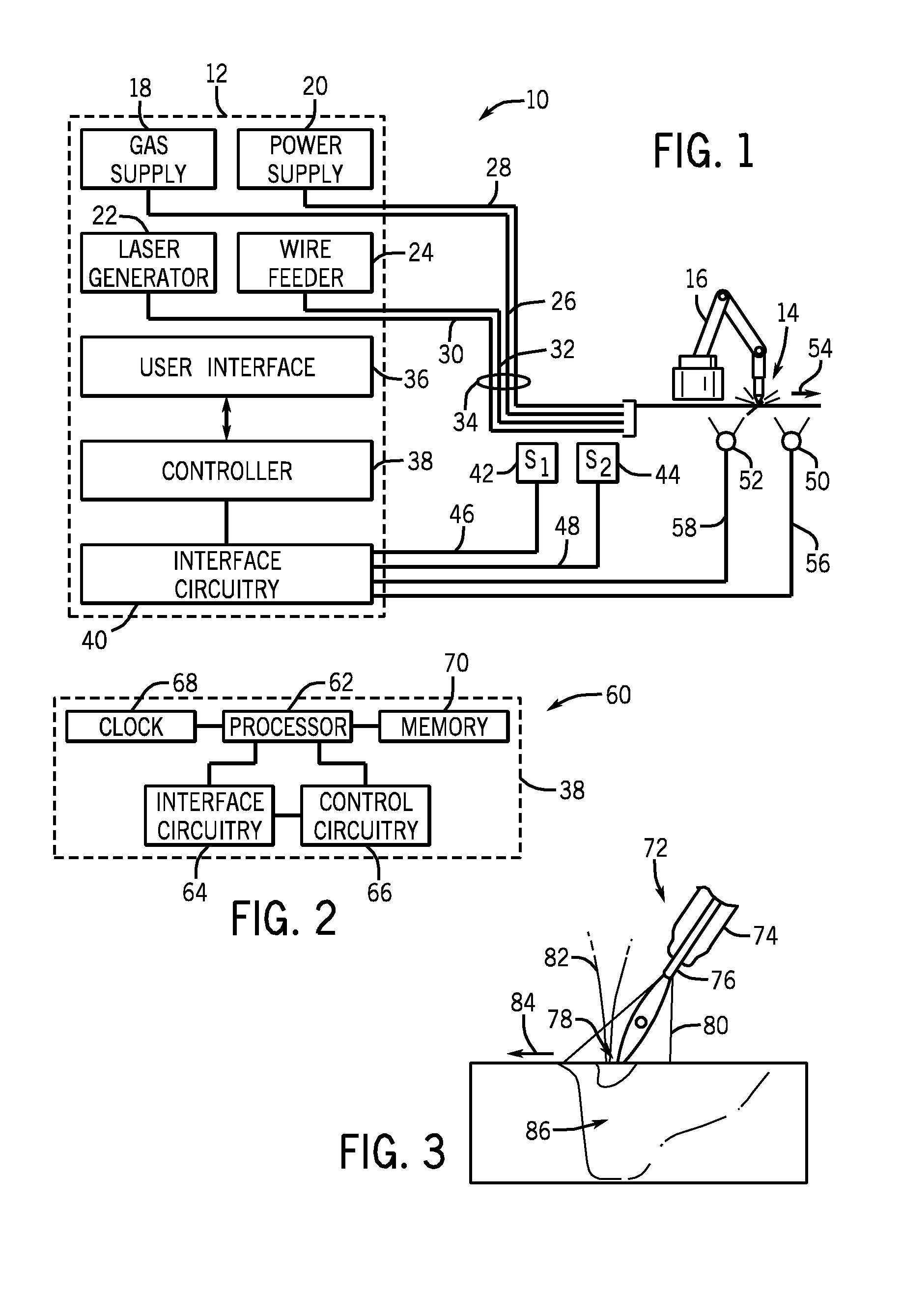
[0005]In an exemplary embodiment, a laser hybrid welding system includes a sensor adapted to acquire data regarding a parameter of a laser hybrid welding operation. The laser hybrid welding system also includes a controller communicatively coupled to the sensor and adapted to receive the acquired data from the sensor and to determine whether the acquired data is indicative of a welding defect. If the acquired data is indicative of a welding defect, the controller is adapted to output a control signal that directs the laser hybrid welding system to attempt to fix the welding defect.
[0006]In an...

Problems solved by technology

While laser beam welding provides speed and deep penetration benefits, such a welding process typically requires tight joint fitup for the laser beam to adequately bridge the gap between the workpieces.
While hybrid welding processes provide good bridgeability at high speeds, such processes are often associated with drawbacks, such as intolerability of gaps in the joint.
These drawbacks often reduce or eliminate the applicability of laser hybrid welding to a variety of applications, such as pipelines, ship building, and automotive manufacturing.
However, laser hybrid welding still poses challenges surrounding gap filling since penetration cannot be adequately controlled when gaps occur in the weld.

Method used


Image

  • Weld defect detection systems and methods for laser hybrid welding
  • Weld defect detection systems and methods for laser hybrid welding
  • Weld defect detection systems and methods for laser hybrid welding

Examples


Embodiment Construction

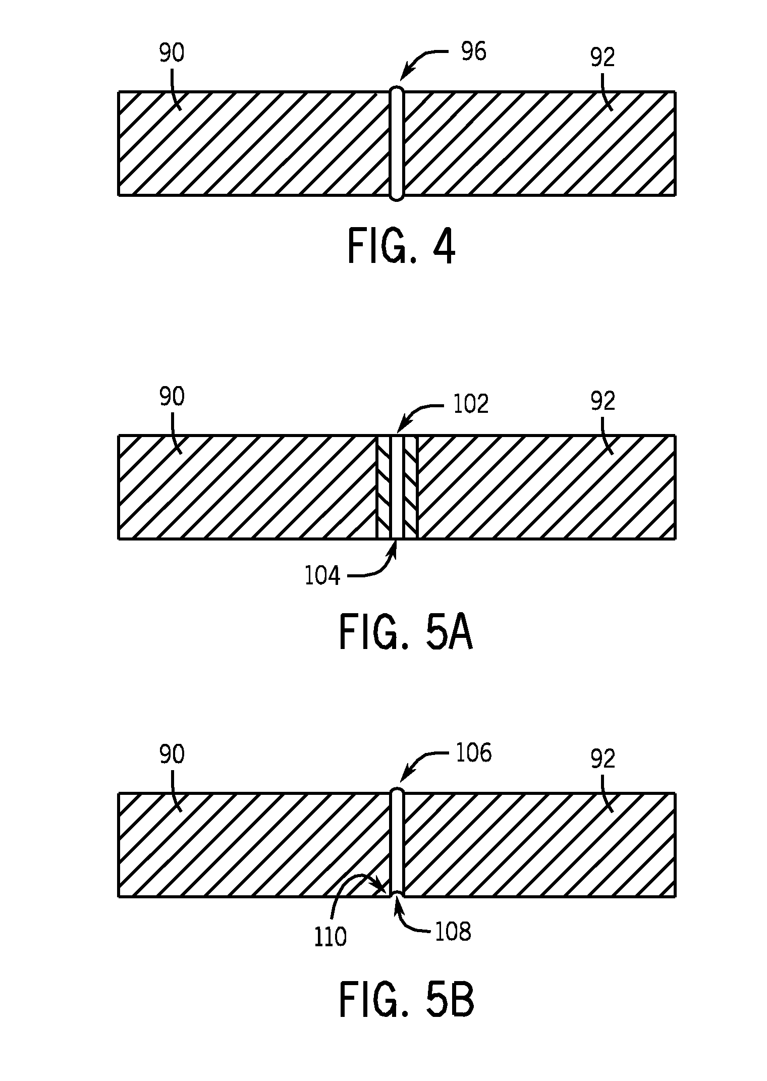
[0018]As described in detail below, embodiments are provided of a laser hybrid welding system adapted to identify and / or to fix a weld defect occurring during a laser hybrid welding process. The disclosed laser hybrid systems may be configured to detect and / or repair weld defects such as those sometimes referred to as “burn-through”, a “suck-back”, inadequate weld reinforcement, improper alignment, cracks, incomplete penetration, and incomplete fusion. To that end, the laser hybrid welding system may include one or more devices that provide feedback to a controller regarding one or more weld parameters. For instance, in one embodiment, the laser hybrid welding system may include sensors, such as a voltage sensor and / or a current sensor that measure the weld voltage and / or amperage during the welding process and transmit the acquired data to the controller for processing. Such parameters may provide an indication of a weld defect that has occurred. For further example, a leading came...


PUM

PropertyMeasurementUnit
Timeaaaaaaaaaa
Lengthaaaaaaaaaa
Sizeaaaaaaaaaa

Abstract

Laser hybrid welding systems adapted to identify and / or fix a weld defect occurring during a laser hybrid welding process are provided. Embodiments of the laser hybrid welding system may include one or more devices that provide feedback to a controller regarding one or more weld parameters. One embodiment of the laser hybrid welding system includes sensors that are adapted to measure the weld voltage and / or amperage during the welding process and transmit the acquired data to the controller for processing. Another embodiment of the laser hybrid welding system includes a lead camera and a lag camera that film an area directly in front of the weld location and directly behind the weld location.

Description

CROSS REFERENCE TO RELATED APPLICATIONS[0001]This application is a Non-Provisional patent application of U.S. Provisional Patent Application No. 61 / 186,116, entitled “Gap Filling with Laser Hybrid Welding”, filed Jun. 11, 2009, which is herein incorporated by reference.BACKGROUND[0002]The invention relates generally to laser hybrid welding systems, and, more particularly, to controllers for laser hybrid welding systems.[0003]Welding is a process that has become increasingly ubiquitous in various industries and applications. A variety of welding techniques have been developed that seek to provide fast welding capabilities with adequate penetration and gap bridegability. While laser beam welding provides speed and deep penetration benefits, such a welding process typically requires tight joint fitup for the laser beam to adequately bridge the gap between the workpieces. Arc welding processes, on the other hand, typically provide for welding more slowly than laser-beam processes, but a...

Claims


Application Information

Patent Timeline
IPC IPC(8): B23K26/00
CPCB23K9/0953B23K31/12B23K26/20B23K37/00B23K26/348B23K31/125B23K26/032B23K9/0956B23K28/02
Inventor ALBRECHT, BRUCE PATRICK
Owner ILLINOIS TOOL WORKS INC
Learn More