Laser-lateral CMT hybrid welding method

A hybrid welding and laser technology, used in laser welding equipment, welding equipment, metal processing equipment, etc., can solve the problems of inability to form complex plasma, sharp weld bottom shape, large distance between arc and laser, etc., to meet the requirements of thin plate Welding deformation requirements, good coupling effect, and the effect of improving coupling effect

Active Publication Date: 2018-02-23
HARBIN INST OF TECH
View PDF6 Cites 2 Cited by
  • Summary
  • Abstract
  • Description
  • Claims
  • Application Information

AI Technical Summary

Problems solved by technology

[0007] Due to the paraxial recombination method and the limitation of the laser action position, the angle between the welding torch and the base metal is not greater than 50°. Therefore, when the welding wire is drawn back and the arc energy is small, the laser and arc are completely separated, and even lose recombination. Effect, image 3 It is a high-speed camera picture when the distance betwee

Method used


Image

  • Laser-lateral CMT hybrid welding method
  • Laser-lateral CMT hybrid welding method
  • Laser-lateral CMT hybrid welding method

Examples


specific Embodiment approach 1

[0032] Specific embodiment one: a kind of laser-lateral CMT composite welding method of the present embodiment, it is carried out according to the following steps:

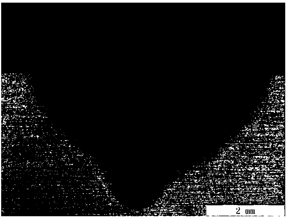
[0033] Step 1: Before welding, process the parts to be welded into V-shaped grooves, I-shaped grooves or Y-shaped grooves according to the plate thickness, and grind and clean the processed grooves and the surfaces on both sides , fix the workpiece to be welded after grinding or cleaning on the welding fixture;

[0034] Step 2: Utilize the fixture to rigidly fix the laser head and the CMT welding torch;

[0035] Step 3: Set welding process parameters:

[0036] The defocus amount is ﹣2~﹢2mm, the laser power is 500~5000W, the angle between the welding torch axis and the base metal is 40~60°, the lateral light wire spacing is 0~2mm, the arc current is 40~150A, and the arc length is corrected. The coefficient is -20%~+20%, the inductance correction coefficient is -10%~+10%, the distance between the light wires along...

specific Embodiment approach 2

[0038] Specific embodiment 2: The difference between this embodiment and specific embodiment 1 is: step 3 sets the welding process parameters:

[0039] The defocus amount is -2~﹢2mm, the laser power is 1000~5000W, the angle between the axis of the welding torch and the base metal is 40~60°, the distance between the lateral filaments is 0~2mm, the arc current is 50~120A, and the arc length is corrected. The coefficient is -20%~+10%, the inductance correction coefficient is -10%~+10%, the distance between the light wires along the welding direction is 1~2mm, the welding speed is 1~4m / min; the welding torch shielding gas adopts pure Ar gas or CO 2 Mixed gas with Ar, the flow rate is 0.4~0.6MPa.

[0040] Others are the same as in the first embodiment.

specific Embodiment approach 3

[0041] Specific implementation mode three: the difference between this implementation mode and specific implementation mode one is: step three sets the welding process parameters:

[0042]The defocus amount is -2~﹢2mm, the laser power is 1000~4000W, the angle between the axis of the welding torch and the base metal is 40~60°, the distance between the lateral filaments is 0~2mm, the arc current is 60~120A, and the arc length is corrected. The coefficient is -20%~+10%, the inductance correction coefficient is -10%~+10%, the distance between the light wires along the welding direction is 1~2mm, the welding speed is 1~3m / min; the welding torch shielding gas adopts pure Ar gas or CO 2 Mixed gas with Ar, the flow rate is 0.4~0.6MPa.

[0043] Others are the same as in the first embodiment.


PUM

PropertyMeasurementUnit
Defocus amountaaaaaaaaaa
Average breaking strengthaaaaaaaaaa

Abstract

The invention relates to a laser-lateral CMT hybrid welding method and relates to the field of material processing engineering. In order to solve the problems that defects are generated in the weldingprocess, and the depth of fusion is reduced, based on conventional laser-arc hybrid welding, a CMT welding gun is transversely arranged to weld a to-be-welded workpiece. By means of the hybrid methodin which the CMT welding gun is transversely arranged, the laser wire spacing can be precisely controlled within the range from 1 mm to 2 mm, the laser key hole stability is ensured, and blowhole defects are avoided. The laser-arc coupling effect is improved, after the method is adopted, the change of the spacing between the arc and the laser is small whether in the arc burning stage or in the arc transitory stage, a good coupling effect can be kept, and the aims of increasing the depth of fusion and improving the energy utilization rate are achieved.

Description

technical field [0001] The invention relates to a laser-lateral CMT composite welding method, which belongs to the field of material processing engineering. Background technique [0002] Laser-arc composite heat source welding has obvious advantages such as good adaptability to weld assembly, small post-weld deformation, good welding consistency and stability, and has higher Controllability and degree of automation. In order to solve the problem of poor welding shape and large post-welding deformation of thin plates, laser-arc hybrid welding technology, especially laser-CMT hybrid welding technology, may be the best choice for thin plate welding, both from the perspective of technology and from the economic point of view. One of the preferred methods. [0003] CMT technology was developed by the Austrian FRONIUS company, which digitally coordinates the wire feeding and droplet transfer process. CMT arc welding has small current, small heat input, small spatter and small d...

Claims


Application Information

Patent Timeline
IPC IPC(8): B23K26/348B23K26/60
CPCB23K26/348B23K26/60
Inventor 雷正龙黎炳蔚卢楠楠陆伟邢希学
Owner HARBIN INST OF TECH
Why Eureka
Try Eureka