Display panel driving method, gate driver, and display apparatus

a technology for display panels and gate drivers, applied in the direction of electric digital data processing, instruments, computing, etc., can solve the problems of increasing the amount of heat generated in the data driver, generating motion blur, and the largest current in the white raster pattern with high appearance frequency, so as to reduce the driving capability, reduce the image quality, and increase the number of pixels

Inactive Publication Date: 2010-12-16
RENESAS ELECTRONICS CORP
View PDF14 Cites 45 Cited by
  • Summary
  • Abstract
  • Description
  • Claims
  • Application Information

AI Technical Summary

Benefits of technology

[0011]However, the present inventor has found a problem that the maximum driving current in the column inversion driving is only ½ of the maximum driving current of the 1H dot inversion driving, and the driving current per unit time is twice the driving current in the normal driving. This causes the data driver to be high temperature. Although the data driver does not result in destruction, if the data driver becomes high temperature, the driving capability is reduced and thereby reducing the image quality.
[0012]Further, in the method disclosed by Okumura that image data in one frame period is monitored to specify the scan order, the circuit size for monitoring the image data increases along with the increase in the number of pixels. Further, the circuit of the gate driver is also complicated, for example requiring eight bits decoder in 256 outputs and 10 bits decoder in 1024 outputs, thus increasing the circuit size.
[0013]An exemplary aspect of the present invention is a method of driving a display panel in which a voltage polarity reverse cycle of a data signal is three or more scan periods, and multiple scan lines are driven by switching between a first and a second scan orders by a predetermined period. The method includes setting a display pattern as a first maximum current pattern, the display pattern in which the multiple scan lines are driven in the first scan order and a number of charge and discharge of the data signal becomes a maximum number, and specifying that the number of charge and discharge of the data signal in case of displaying the first maximum current pattern in the second scan order is to be ½ of the number of charge and discharge of the data signal in case of displaying the first maximum current pattern in the first scan order. Further, the voltage polarity reverse cycle for specifying the first and the second orders is one frame period. Then by switching at least two or more scan orders having different maximum current patterns by a predetermined period, the average driving current of the data signals in a particular display pattern can be reduced, and thereby reducing the highest attainable temperature of the data driver.
[0014]The driving method of the present invention enables to reduce the average driving current of data signals in a particular display pattern and reduce the highest attainable temperature of data driver without monitoring image data and also increasing the circuit size of the gate driver.

Problems solved by technology

However, if a liquid crystal panel is normally black, the driving current becomes the largest in the white raster pattern with high appearance frequency.
Low response speed of the liquid crystals causes to generate motion blur.
However, if 1H dot inversion driving is performed in the double-speed drive, the driving current increases and the amount of heat generated in the data driver increases, thereby increasing the temperature too high and possibly leading to destroy the data driver.
However, the present inventor has found a problem that the maximum driving current in the column inversion driving is only ½ of the maximum driving current of the 1H dot inversion driving, and the driving current per unit time is twice the driving current in the normal driving.
This causes the data driver to be high temperature.
Although the data driver does not result in destruction, if the data driver becomes high temperature, the driving capability is reduced and thereby reducing the image quality.
Further, the circuit of the gate driver is also complicated, for example requiring eight bits decoder in 256 outputs and 10 bits decoder in 1024 outputs, thus increasing the circuit size.

Method used


Image

  • Display panel driving method, gate driver, and display apparatus
  • Display panel driving method, gate driver, and display apparatus
  • Display panel driving method, gate driver, and display apparatus

Examples


first exemplary embodiment

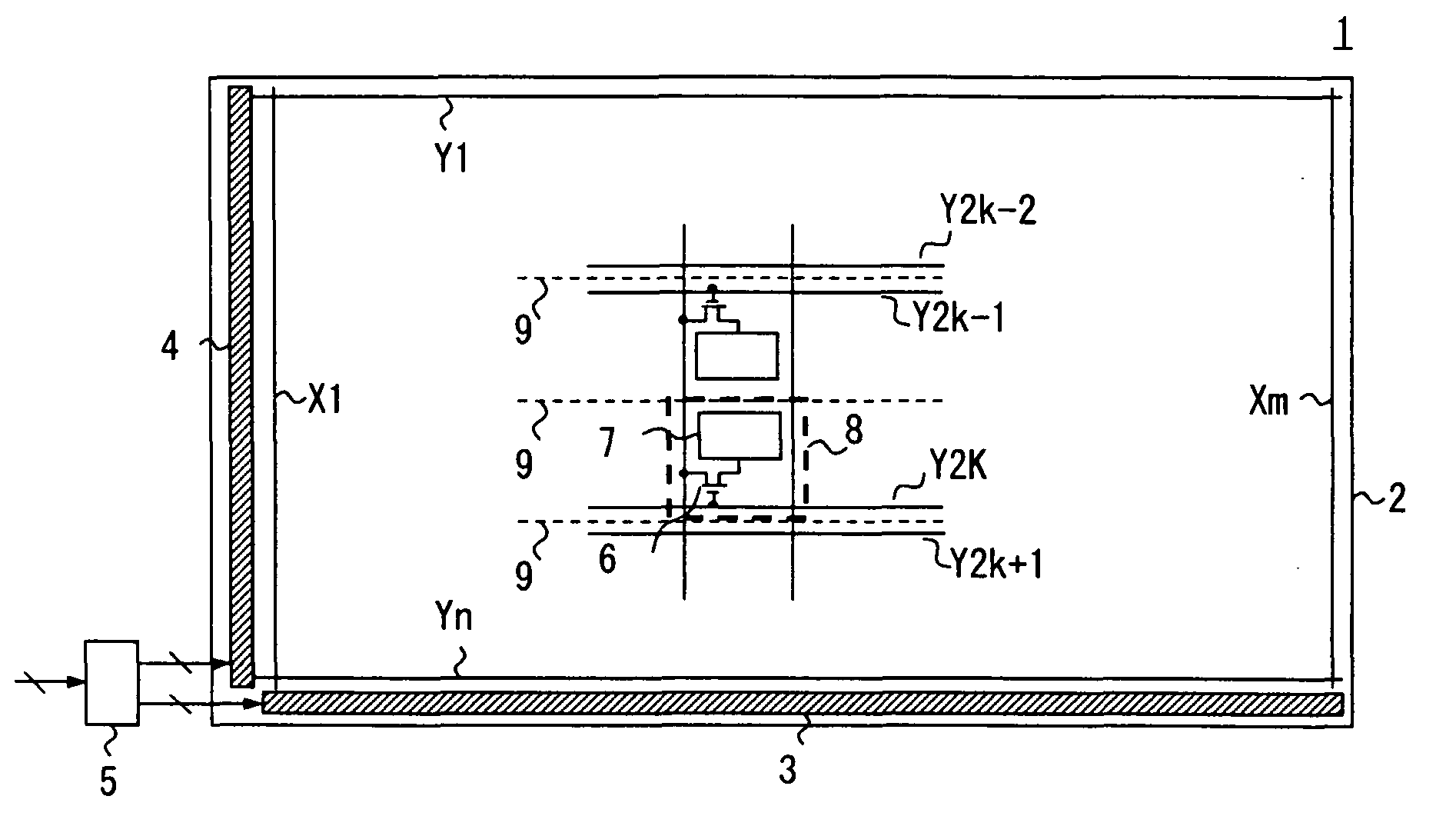
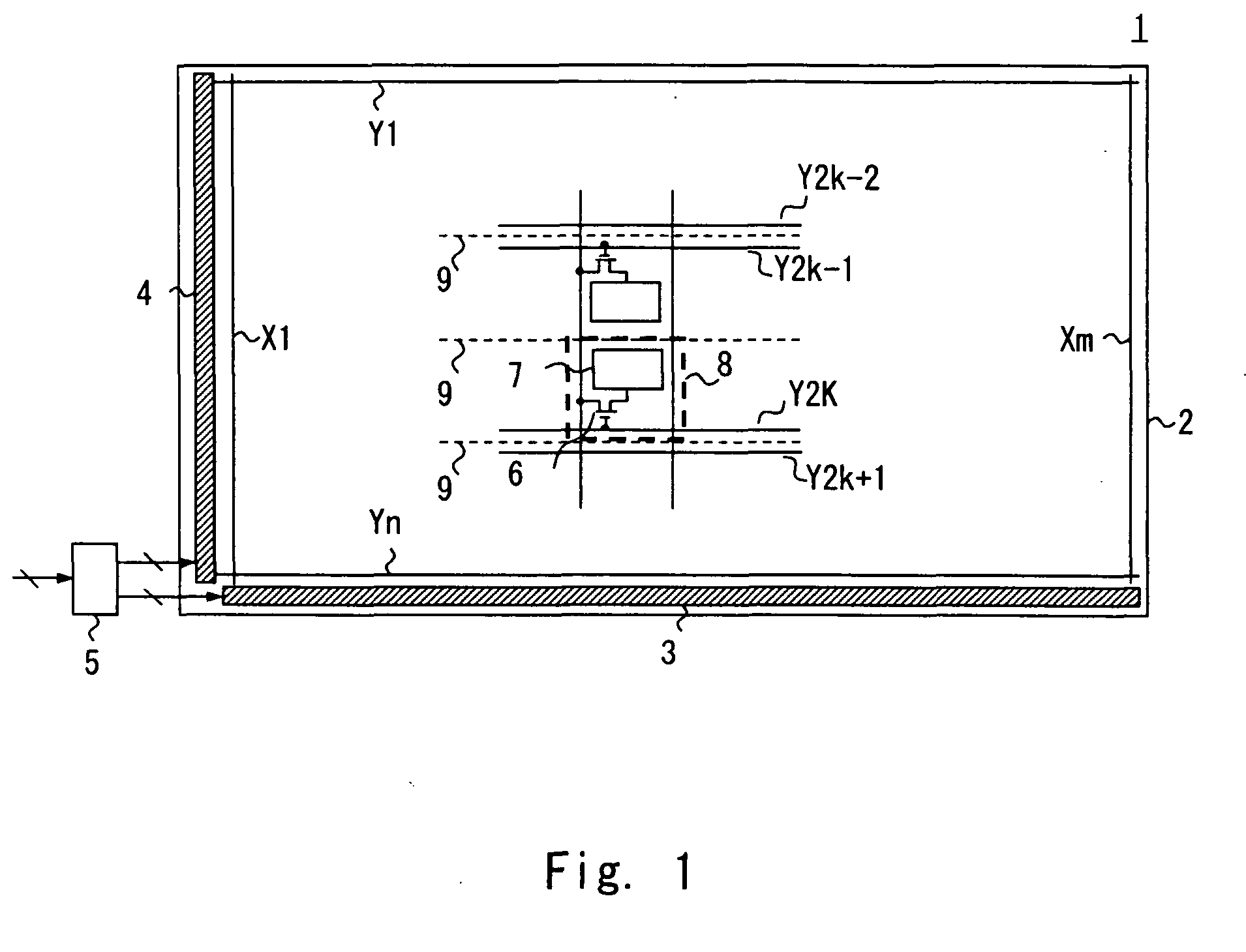
[0047]The configuration of a display device according to a first exemplary embodiment of the present invention is explained with reference to FIG. 1. FIG. 1 is a block diagram illustrating the configuration of a liquid crystal display 1 according to this exemplary embodiment. As illustrated in FIG. 1, the liquid crystal display 1 is provided with a liquid crystal display panel 2, a data driver 3, a gate driver 4, and a timing controller 5. Although not illustrated in the drawing, the liquid crystal display 1 is provided with a backlight that illuminates the display from the back of the liquid crystal display panel 2, and a power supply that supplies power supply voltage to the data driver 3 and the gate driver 4, for example.

[0048]Multiple data lines X1 to Xm extending in the column (vertical) direction, and multiple scan lines Y1 to Yn extending in the row (horizontal) direction are formed in a grid pattern. A liquid crystal cell 8 which functions as a display cell is formed in the...

second exemplary embodiment

[0104]A driving method of a display panel according to a second exemplary embodiment of the present invention is explained with reference to FIGS. 6 to 8. This exemplary embodiment explains an example of using the scan orders E, F, G, and H instead of the scan order A, B, C, and D of the first exemplary embodiment. Note that the display device with similar configuration as FIG. 1 can be used for the display device, thus the explanation is omitted. FIG. 6 illustrates the scan orders of each scan line in one scan block in this exemplary embodiment.

[0105]In the scan order E, the first and second scan groups are forward scan, and the third and fourth scan groups are backward scan. That is, the scan lines are driven in the order of Y1→Y2→Y3→Y4→Y6→Y5→Y8→Y7. In the scan order F, the first and second scan groups are backward scan, and the third and fourth scan groups are backward scan. That is, the scan lines are driven in the order of Y2→Y1→Y4→Y3→Y5→Y6→Y8.

[0106]In the scan order G, the fir...

third exemplary embodiment

[0120]A driving method of a display panel according to a third exemplary embodiment of the present invention is explained with reference to FIG. 9. This exemplary embodiment explains the example of using scan order P, Q, R, and S instead of the scan orders A to D, and E to H in the first and second exemplary embodiments. Note that the display device with similar configuration as FIG. 1 can be used for the display device, thus the explanation is omitted. FIG. 9 illustrates the scan order of each scan line in one scan block in this exemplary embodiment.

[0121]In the scan order P, the first, second, and third scan groups are forward scan, and the fourth scan is backward scan. That is, the scan lines are driven in the order of Y1→Y2→Y3→Y4→Y5→Y6→Y8→Y7. In the scan order Q, the first, second, and third scan groups are backward scan, and the fourth scan group is forward scan. That is, the scan lines are driven in the order of Y2→Y1→Y4→Y3→Y6→Y5→Y7→Y8.

[0122]In the scan order R, the first, thi...


PUM


Abstract

A method of driving a display panel in which a voltage polarity reverse cycle of a data signal is three or more scan periods, and multiple scan lines are driven by switching between a first and a second scan orders by a predetermined period. The method includes setting a display pattern as a first maximum current pattern, the display pattern in which the multiple scan lines are driven in the first scan order and a number of charge and discharge of the data signal becomes a maximum number, and specifying that the number of charge and discharge of the data signal when displaying the first maximum current pattern in the second scan order is to be ½ of that of the data signal when displaying the first maximum current pattern in the first scan order. Further, the voltage polarity reverse cycle for specifying the first and the second scan orders is one frame period.

Description

INCORPORATION BY REFERENCE[0001]This application is based upon and claims the benefit of priority from Japanese patent application No. 2009-141378, filed on Jun. 12, 2009, and Japanese patent application No. 2010-75862, filed on Mar. 29, 2010, the disclosures of which are incorporated herein in their entirety by reference.BACKGROUND[0002]1. Field of the Invention[0003]The present invention relates to display panel driving method, a gate driver, and a display apparatus, and particularly to a display panel driving method that switches multiple scan orders by a predetermined period to drive, a gate driver, and a display apparatus.[0004]2. Description of Related Art[0005]A matrix liquid crystal display panel including liquid crystal cells arranged in a matrix is one of the most typical display devices. Liquid crystal cells, scan lines for selecting rows of the liquid crystal cells, and data lines for supplying data signals are provided in a liquid crystal display panel. The scan line an...

Claims


Application Information

Patent Timeline
Patent Type & Authority Applications(United States)
IPC IPC(8): G06F3/038
CPCG02F1/134336G09G3/3614G09G3/3648G09G3/3677G09G2300/0426G09G2300/0443G09G2300/0452G09G2310/0218G09G2320/0209G09G2330/021
Inventor HASHIMOTO, YOSHIHARU
Owner RENESAS ELECTRONICS CORP
Why Eureka
Try Eureka