Image processing device and image processing method
- Summary
- Abstract
- Description
- Claims
- Application Information
AI Technical Summary
Benefits of technology
Problems solved by technology
Method used
Image

Examples
first embodiment
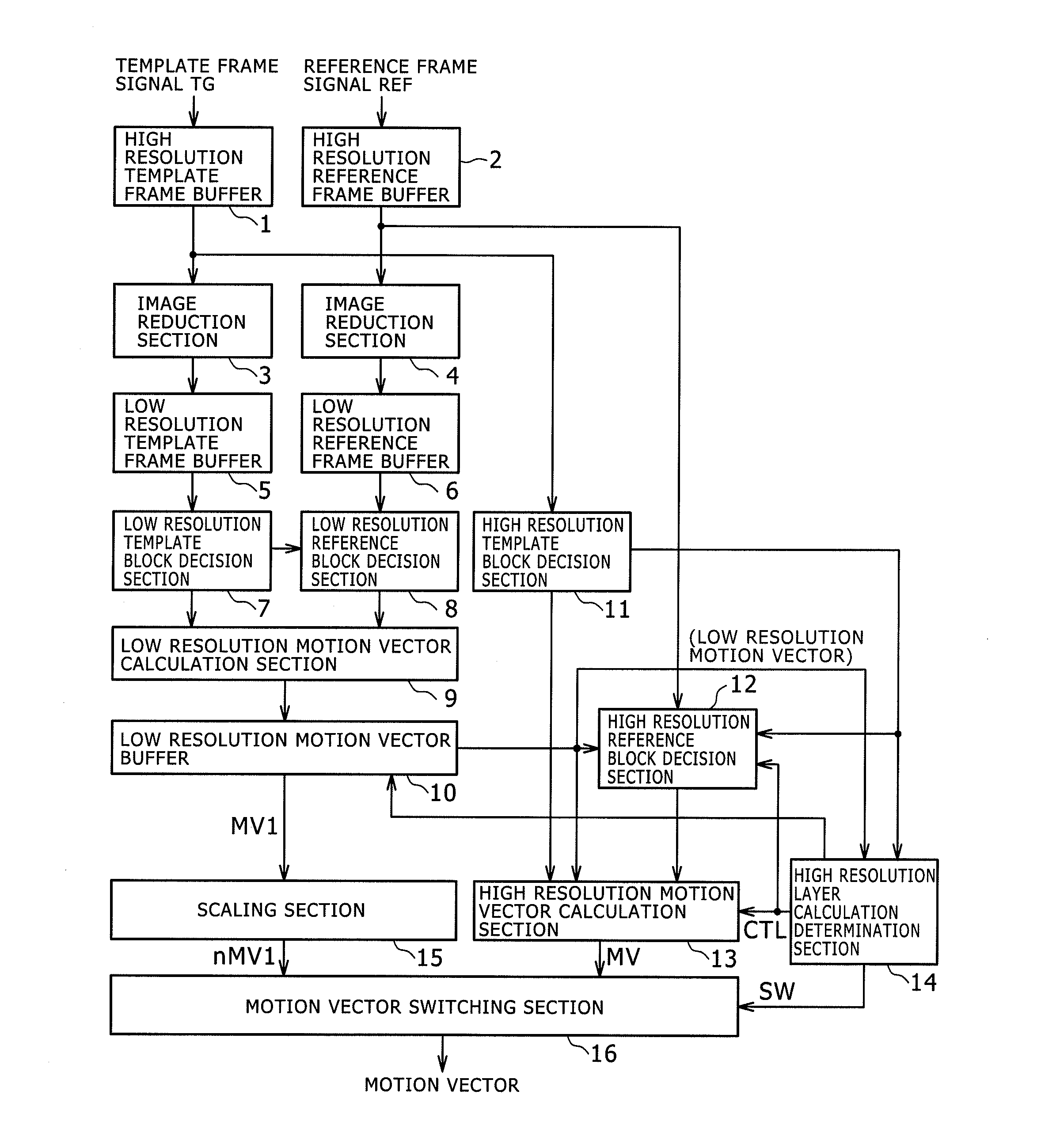
[0107]FIG. 1 is a block diagram illustrating a configuration example of the major components of the image processing device according to a first embodiment of the present invention. It should be noted that not only the image processing device according to this first embodiment but also others according to the embodiments described later are, for example, motion vector detectors adapted to detect a motion vector from a moving image signal.
[0108]The first embodiment uses only information in the low resolution layer to determine whether to calculate a motion vector for each of the high resolution template blocks. In this example, information of only a low resolution image, i.e., reduced image of the original image, is used, thus providing further reduced processing cycles and power consumption.
[0109]As illustrated in FIG. 1, in this example, a moving image signal of each of the previous frames delayed by one frame is loaded into a high resolution template frame buffer 1 as a template f...
second embodiment
[0171]FIG. 10 is a block diagram illustrating a configuration example of the major components of the image processing device according to a second embodiment of the present invention. In FIG. 10, like components as those of the image processing device according to the first embodiment shown in FIG. 1 are designated by like reference numerals.
[0172]This second embodiment and other several embodiments which will be described below are completely identical to the first embodiment in configuration and processes except for information supplied to the high resolution layer calculation determination section 14 and the detail of the processes performed using that information.
[0173]As with the first embodiment, the second embodiment also uses only the information in the low resolution layer to determine whether or not to calculate a motion vector for each of the high resolution template blocks.
[0174]In the second embodiment, the high resolution layer calculation determination section 14 comp...
third embodiment
[0191]FIG. 12 is a block diagram illustrating a configuration example of the major components of the image processing device according to a third embodiment of the present invention. In FIG. 12, like components as those of the image processing device according to the first embodiment shown in FIG. 1 are designated by like reference numerals.
[0192]As with the first and second embodiments, the third embodiment also uses only the information in the low resolution layer to determine whether to calculate a motion vector for each of the high resolution template blocks.
[0193]In the third embodiment, the high resolution layer calculation determination section 14 calculates an edge magnitude from image information of the low resolution template block at the position associated with the high resolution template block to determine, based on the edge magnitude, whether to calculate a motion vector in the high resolution layer.
[0194]If the edge magnitude is large in the image information of the ...
PUM
 Abstract
Description
Claims
Application Information
PatSnap Eureka turns technology decisions into work you can execute. Powered by our Innovation Knowledge Graph, it runs expert workflows across engineering, life sciences, materials and intellectual property. Get your review-ready output in minutes.


