Method of design optimisation

a design optimization and process technology, applied in the field of design optimization, can solve the problems of high fidelity, computational cost, and restricting the outcome of the optimisation process, and achieve the effect of reducing the cost of the optimisation process

Inactive Publication Date: 2010-12-16
AIRBUS OPERATIONS LTD
View PDF1 Cites 38 Cited by
  • Summary
  • Abstract
  • Description
  • Claims
  • Application Information

AI Technical Summary

Benefits of technology

[0048]Preferably the nodes defined in step a)i) are a 3D lattice of nodes, particularly when complex geometries are involved. It is also preferable that the set of nodes defined in step a)i) comprises an active set of nodes which can be moved in step d)i) and a fixed set of nodes which cannot be moved in step d)i). This enables continuity to be maintained between the geometry to be optimised and any adjoining geometries.

Problems solved by technology

However, it is now also commonplace within the aerodynamics industry to employ high fidelity computational fluid dynamics (CFD), a computationally expensive method, as a design quality assessment tool.
If the parameterisation is too inflexible the number and variation of the possible shapes is restricted, thereby restricting the outcome of the optimisation process.
Conversely, a very flexible parameterisation is likely to require a large number of design variables.
If the number of design variables is too large the design space becomes inefficient and the search process will struggle to find the optimum design.
However, for complex geometries this method typically requires a large number of design variables.
However, it is difficult to recreate the CAD model from the deformed CFD mesh precisely.
Although the FFD method presented by Sederberg and Parry is a powerful deformation tool it does have limitations.
These restrictions limit the types of deformations achievable.
With respect to shape optimisation this increases the complexity of choosing the design variables needed to achieve the required deformation types.
This is further complicated if the control lattice contains internal control points.
However, the control lattice is still restricted to a parallelepiped shape.
When using a NURBS basis with the FFD methods the lattice freezing process is complicated as a numerical search technique is needed.
Whichever search process is used can be very computationally expensive.
Therefore the computational expense required to freeze the lattice is only encountered once.
However, the use of lattices which are too complex can produce unpredictable results.
While the EFFD method does enable a greater range of deformations when compared to the original FFD methods, it loses some of the flexibility due to the automatic calculation of intermediate lattice points.
It is also clear that the numerical search techniques needed to freeze the EFFD lattice are time consuming and computationally expensive.
However, during a design optimisation process freezing the lattice still only needs to occur once to freeze the base design.
However, if the number of object points is greater than the number of lattice control points the system of equations is over-determined and hence there is no unique solution.

Method used


Image

  • Method of design optimisation
  • Method of design optimisation
  • Method of design optimisation

Examples


case study

[0101

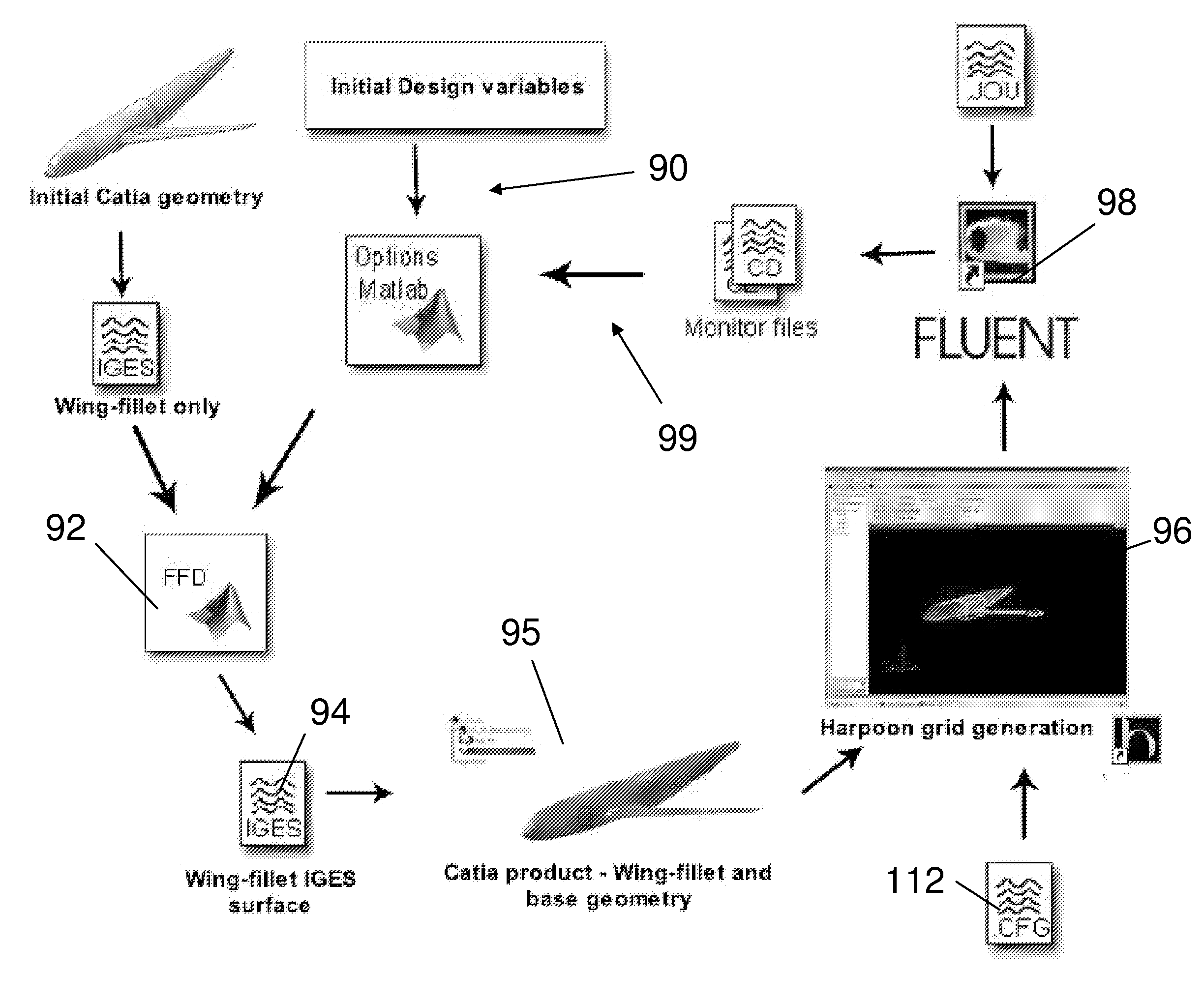
[0102]In order to examine the practicalities of implementing the proposed FFD parameterisation and CAD integration methods, the set-up and initialisation of a case study is presented. As discussed above, the ultimate aim of this case study is the aerodynamic optimisation of a faring placed around the wing-fuselage junction (termed the “wing-fillet”) of a typical transonic passenger aircraft. This case study has been chosen as it requires the manipulation of a complex geometry with numerous geometrical constraints to test the proposed methodology. It is also an area of the flow field within which improvements may be possible.

[0103]A. Optimisation Objectives and Constraints

[0104]This case study aims to minimise the total drag experienced by the aircraft by only manipulating the shape of a wing-fillet. Each design is subject to the following aerodynamic constraints:

[0105]1. Angle of attack (AoA): 1 degree; and

[0106]2. Mach number, M=0.75.

[0107]These constraints are the design crui...


PUM


Abstract

A method of design optimization includes: a) producing a first computer model of a first geometry, the first computer model including: i) a set of nodes; and ii) a set of construction points each having a position defined by a local co-ordinate system; b) producing a computational fluid dynamics (CFD) mesh from the first computer model; c) using the CFD mesh to produce a measure of the fluid dynamic performance of the first geometry, such as drag count or lift coefficient; d) producing a new computer model of a new geometry by: i) moving one or more of the nodes; and ii) recalculating the positions of the construction points in response to movement of the one or more nodes; e) producing a computational fluid dynamics (CFD) mesh from the new computer model; f) using the CFD mesh to produce a measure of the fluid dynamic performance of the new geometry, such as drag count or lift coefficient; and g) identifying an optimal geometry using the fluid dynamic performance measurements of the first and new geometries produced in steps c and f.

Description

FIELD OF THE INVENTION[0001]The present invention relates to a method of design optimisation.BACKGROUND OF THE INVENTION[0002]Over recent years the advancement made in computing power has revolutionised the process of designing aerodynamic structures. Traditional trial and error methods have been replaced by automated optimisation routines. The general idea is that by parameterising a design by a series of design variables and then automating design generation and assessment, a search process can be used to find optimum designs. During such an optimisation process hundreds / thousands of designs can be produced that have to be evaluated. It is therefore important to keep the computing resources needed per design to a minimum. However, it is now also commonplace within the aerodynamics industry to employ high fidelity computational fluid dynamics (CFD), a computationally expensive method, as a design quality assessment tool.[0003]A typical optimisation process using CFD analysis is ill...

Claims


Application Information

Patent Timeline
Patent Type & Authority Applications(United States)
IPC IPC(8): G06F17/50G06F17/10G06G7/57
CPCG06F2217/46G06F17/5095G05B17/02G06F30/15G06F2113/28Y02T90/00
Inventor HOLDEN, CARRENNURDIN, ADAMBRESSLOFF, NEIL W.KEANE, ANDREW K.
Owner AIRBUS OPERATIONS LTD
Why Eureka
Try Eureka