Method of modeling dynamic characteristics of a flight vehicle

a flight vehicle and dynamic characteristics technology, applied in the direction of vehicle position/course/altitude control, process and machine control, instruments, etc., can solve the problems of time-consuming, complicated and time-consuming, existing methods of high-order flight vehicle dynamics and output files for use in simulation, analysis, and flight vehicle control design, etc., to achieve satisfactory complexity level, easy modification, and increase the complexity of flight vehicle models

Inactive Publication Date: 2010-12-16
FALANGAS ERIC T
View PDF13 Cites 99 Cited by
  • Summary
  • Abstract
  • Description
  • Claims
  • Application Information

AI Technical Summary

Benefits of technology

[0018]The analyst may gradually increase the complexity of the flight vehicle models by adding parameters such as tail-wags-dog, slosh, bending, detailed actuator models, load torques and other dynamic effects to a satisfactory level of complexity.
[0019]The present invention therefore addresses the needs of the flight control analyst, who can easily transform the trajectory, aero, and mass properties data into linear state-space models for a quick evaluation of system performance at fixed flight conditions, all within one modeling tool. The program can be used to analyze various flight vehicles such as launch vehicles, rocket-planes, reentry vehicles, space stations, satellites, and high performance aircraft that use rocket engines, reaction jets, differential throttling, control moment gyros (CMG), reaction wheels (RW), and control surfaces. A model can easily be modified to a different configuration by changing the input data. The input data comprises trajectory data, aerodynamic data, mass properties, engine parameters, reaction control thrusters, orie

Problems solved by technology

Existing methods of modeling high order flight vehicle dynamics and generating an output file for us

Method used


Image

  • Method of modeling dynamic characteristics of a flight vehicle
  • Method of modeling dynamic characteristics of a flight vehicle
  • Method of modeling dynamic characteristics of a flight vehicle

Examples


Embodiment Construction

[0032]In the following description of the present invention reference is made to the accompanying drawings which form a part thereof, and in which is shown, by way of illustration, exemplary embodiments illustrating the principles of the present invention and how it may be practiced. It is to be understood that other embodiments may be utilized to practice the present invention and structural and functional changes may be made thereto without departing from the scope of the present invention.

Introduction

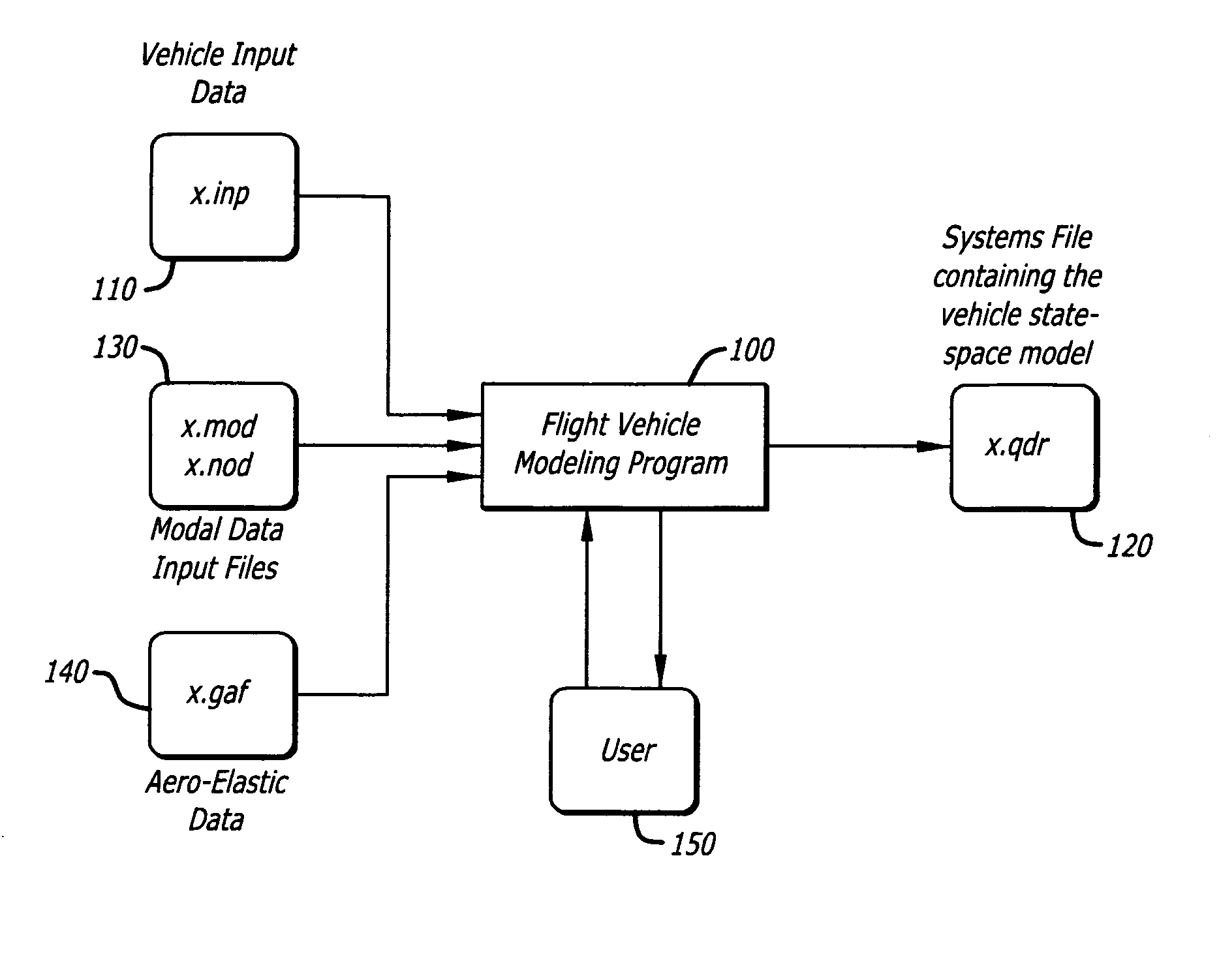
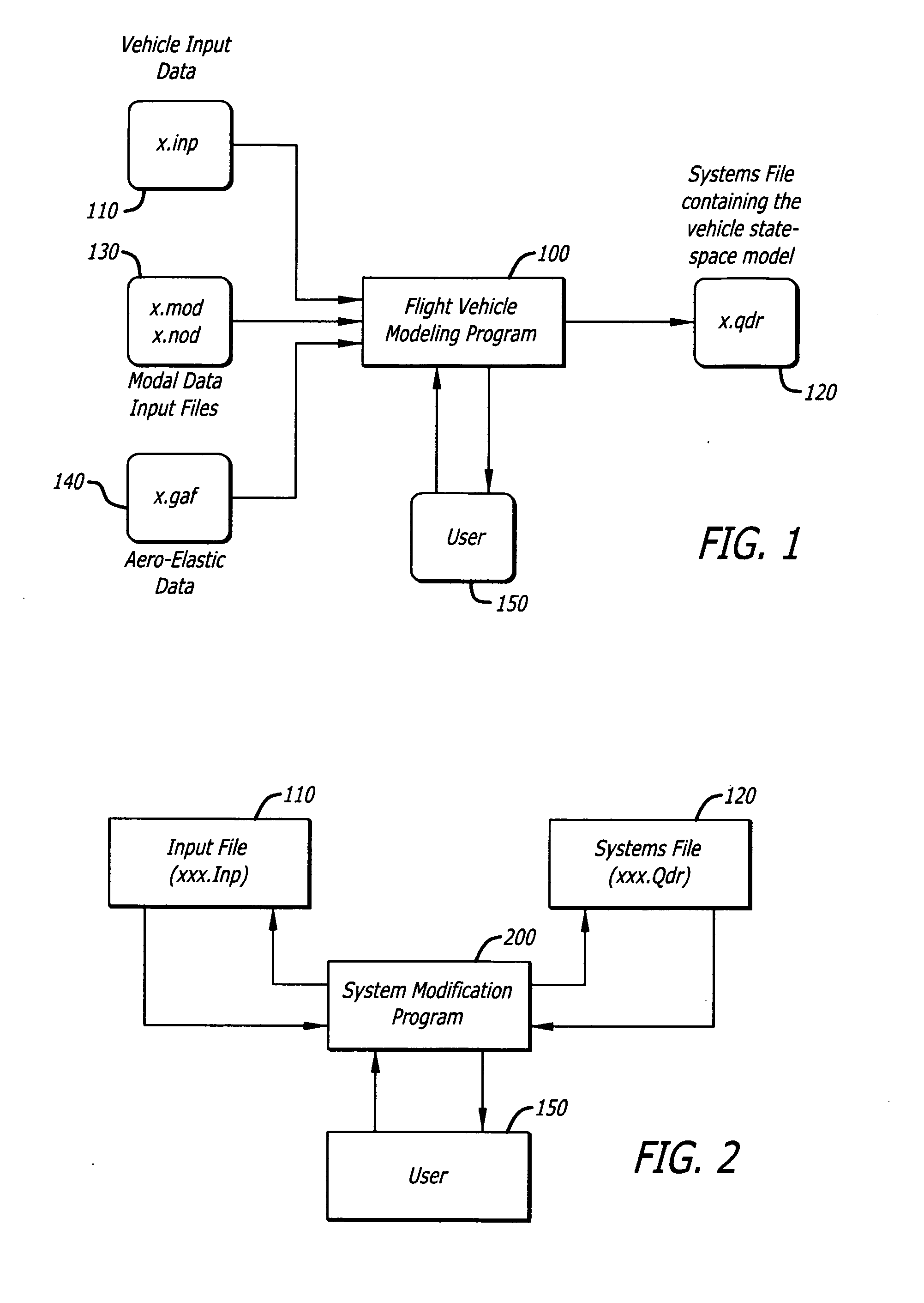
[0033]The present invention is a collection of flight vehicle modeling and analysis programs and other related utilities, used to create complex state-space models of flight vehicles for linear stability and performance analysis. The dynamic models may vary, from simple rigid body to very complex models that may include high order dynamics, such as actuators, tail-wag-dog, slosh and flexibility with hundreds of structural modes. The program is interactive and uses a graphical user in...


PUM


Abstract

The present invention models dynamic behavior of flight vehicles for simulation, analysis, and design. The present invention allows a user to define the complexity of a flight vehicle model, and such models may be simple rigid body models, models of medium complexity, or very complex models including high order dynamics comprising hundreds of structural flexibility modes and variables related to aero-elasticity, fuel sloshing, various types of effectors, tail-wags-dog dynamics, complex actuator models, load-torque feedback, wind gusts, and other parameters impacting flight vehicles. The present invention accommodates and analyzes multiple vehicle and actuator concepts and configurations as defined in flight vehicle input data, which specifies flight vehicle parameters at a steady-state condition for modeling flight vehicle response to dynamic forces and flight control commands with respect to steady state operation.

Description

CROSS-REFERENCE TO RELATED APPLICATIONS[0001]This application claims priority to a provisional application having Ser. No. 61 / 268,434, filed Jun. 13, 2009, the contents of which are hereby incorporated by reference in their entirety.BACKGROUND OF THE INVENTION[0002]The present invention generally relates to a method of modeling dynamic characteristics of flight vehicles. Specifically, the present invention relates to a method of compiling input data defining characteristics of a flight vehicle and generating system output data for performing simulation, analysis, and design on the flight vehicle control system.[0003]Existing methods of modeling high order flight vehicle dynamics and generating an output file for use in simulation, analysis, and design of flight vehicle controls are complicated and time consuming. The performance quality of flight vehicles, such as launch vehicles, re-entry vehicles, and high performance aircraft, is generally studied in two distinct, though related,...

Claims


Application Information

Patent Timeline
IPC IPC(8): G06G7/48
CPCG06F17/5095G05B17/02G06F30/15
Inventor FALANGAS, ERIC T.
Owner FALANGAS ERIC T
Why Eureka
Try Eureka