
Dpf accumulation amount estimating apparatus

Inactive Publication Date: 2010-12-23
MITSUBISHI HEAVY IND LTD
View PDF9 Cites 18 Cited by
  • Summary
  • Abstract
  • Description
  • Claims
  • Application Information

AI Technical Summary

Benefits of technology

[0022]In view of the problems with the prior art described above, an object of the present invention is to provide a DPF accumulation amount estimating apparatus which uses an integrated PM accumulation amount estimation logic combining the difference between an engine PM emission amount and a PM regeneration amount and a DPF differential pressure model, thereby achieving improved estimation accuracy with minimized influences of changes in an exhaust gas flow rate and the like.
[0028]According to the present invention, the DPF accumulation amount estimating apparatus has a PM emission amount model in which a PM emission amount is set on the basis of the operating condition of an engine, a PM regeneration amount model in which a PM regeneration amount is set on the basis of the temperature difference between an outlet temperature and an inlet temperature of the DPF, and a DPF differential pressure model in which a PM accumulation amount is set on the basis of the differential pressure between an exhaust gas flow rate and the DPF, wherein the emission amount from the PM emission amount model, the regeneration amount from the PM regeneration amount model, and the corrected PM accumulation amount, which has been obtained by correcting the estimated value of the PM accumulation amount from the DPF differential pressure model by using a coefficient K determined on the basis of an engine speed and an engine fuel injection amount are used to calculate an estimated PM accumulation amount of the DPF. Therefore, even if a PM emission amount map and a PM regeneration amount map contain errors, the errors are corrected by an estimated value from the DPF differential pressure model, thus leading to an improved accuracy for estimating the PM accumulation amount.
[0030]Further, the corrected amount of the PM accumulation amount is calculated by multiplying the estimation error between the estimated value of the PM accumulation amount from the DPF differential pressure model and the estimated PM accumulation amount by the aforesaid K, and the estimated PM accumulation amount is calculated by adding the corrected PM accumulation amount to the value obtained by subtracting the regeneration amount from the PM regeneration amount model from the emission amount from the PM emission amount model. Thus, the coefficient K taking into account terms including the engine speed and the fuel injection amount of the engine, which is an exhaust gas flow rate, is used to estimate the PM accumulation amount, so that the influences of the exhaust gas flow rate are reduced with a resultant higher estimation accuracy of the estimated PM accumulation amount.
[0031]Further, the coefficient K changes with the engine speed and the fuel injection amount of the engine, and the coefficient K is determined such that it increases as the engine speed and the fuel injection amount of the engine increase if the engine speed and the fuel injection amount of the engine are predetermined values or more. Thus, setting the coefficient K such that it increases with increasing engine speed and fuel injection amount of the engine enhances the correction based on an estimated amount from the DPF differential pressure model in a range wherein the exhaust gas flow rate of the engine increases and the reliability of the DPF differential pressure model is high. The estimated PM accumulation amount based on the operating condition of the engine can be corrected in the enhanced correction environment, resulting in higher estimation accuracy for the estimated PM accumulation amount.
[0032]Further, the coefficient K is set to zero when changes in the engine speed and the fuel injection amount of the engine are predetermined values or more, and no correction is carried out on the estimated value of the PM accumulation amount from the DPF differential pressure model. Hence, in the case where changes in the engine speed and the fuel injection amount of the engine are the predetermined values or more, the exhaust gas flow rate also significantly changes, leading to deteriorated reliability of the estimated PM accumulation amount from the DPF differential pressure model. For this reason, the estimation accuracy for the estimated PM accumulation amount is improved by setting the coefficient K to zero so as not to make any correction under such changes.

Problems solved by technology

The metal type is easy to handle, but has a low PM trapping efficiency of 50% to 60%.
For this reason, if an actual PM emission amount exceeds the aforesaid estimation elements, then the estimated PM amount output by the PM accumulation amount estimation logic 14a will significantly deviate from an actual accumulation amount as time elapses, and present a problem especially if the actual accumulation amount becomes the estimated PM amount or more.
However, it is difficult to measure the relationship among the DPF differential pressure, the exhaust gas flow rate, and the PM accumulation amount over the entire engine operation range with high accuracy.

Method used


Image

  • Dpf accumulation amount estimating apparatus
  • Dpf accumulation amount estimating apparatus
  • Dpf accumulation amount estimating apparatus

Examples


first embodiment

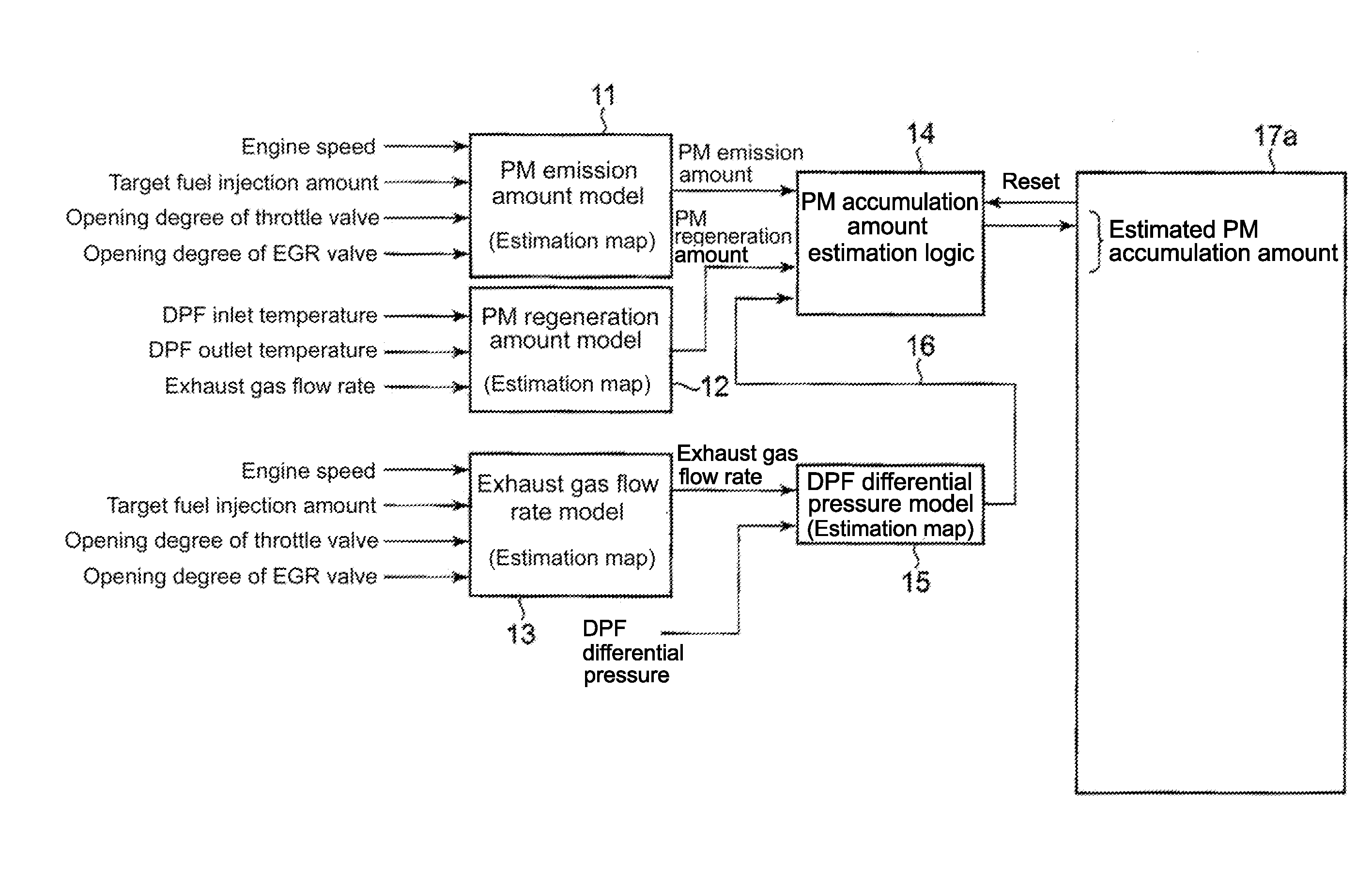
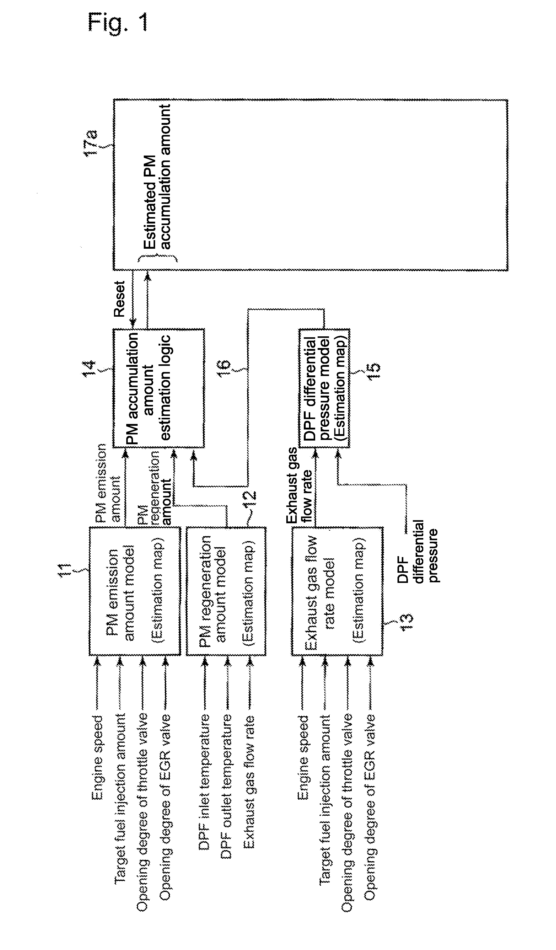
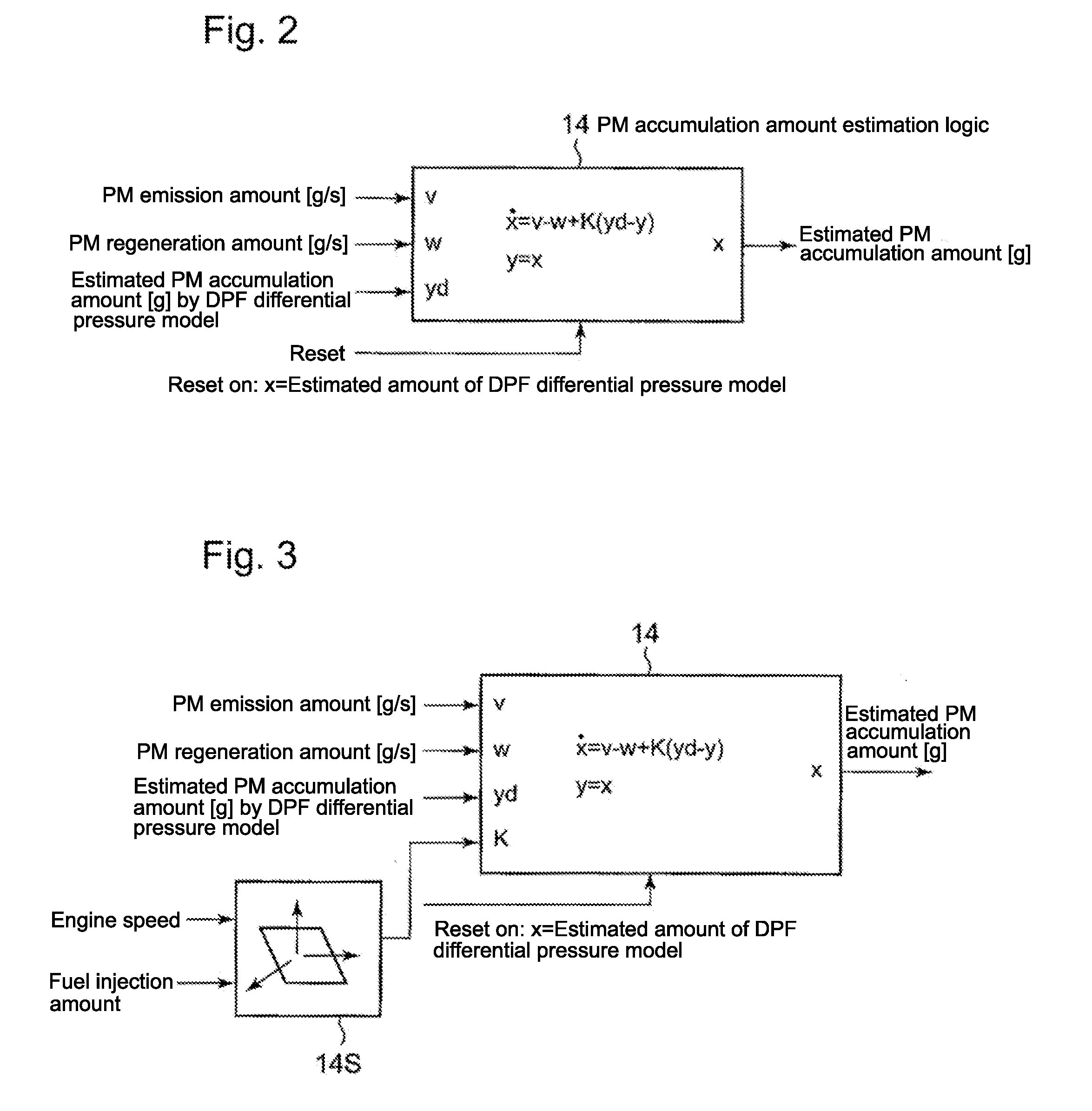
[0041]FIG. 1 is a block diagram of the estimation of a PM accumulation amount in a regeneration controller of a DPF in accordance with the present invention, and FIG. 2 is an enlarged view of PM accumulation amount estimation logic 14 in FIG. 1. FIG. 6 is a longitudinal sectional diagram of a typical DPF apparatus.

[0042]In FIG. 6, reference numeral 13 denotes an exhaust pipe in communication with an exhaust port of an engine (not shown), and reference numeral 50 denotes a DPF apparatus connected to the exhaust pipe 13. The DPF apparatus 50 includes a DPF 1 accommodated in a DPF main unit 2 and a pre-stage oxidation catalyst 3 installed on the upstream side of the DPF 1.

[0043]An exhaust gas from the engine passes through an inlet chamber 4 from the exhaust pipe 13 and reaches the pre-stage oxidation catalyst 3 and the exhaust gas is oxidized by the pre-stage oxidation catalyst 3. The oxidative heat generated at that time causes the DPF 1 to rise to 600 to 650° C. in temperature to bu...

second embodiment

[0062]FIG. 3 is a block diagram illustrating a second embodiment of a PM accumulation amount estimation logic in a regeneration controller of a DPF according to the second embodiment of the present invention.

[0063]In the second embodiment, as illustrated in FIGS. 5(A) and (B), the aforesaid K is determined such that it changes according to the engine speed and the fuel injection amount of the engine (14s in FIG. 3), increases with the engine speed, as illustrated in FIG. 5(A), and increases as the fuel injection amount of the engine increases, as illustrated in FIG. 5(B).

[0064]With this arrangement, the coefficient K increases as the engine speed and the fuel injection amount of the engine increase, and the estimated PM accumulation amount is increased as the exhaust gas flow rate of the engine increases, thus making it possible to correct the estimated PM accumulation amount according to the operating condition of the engine. The result is an improved estimation accuracy of the est...


PUM


Abstract

A DPF accumulation amount estimating apparatus uses an integrated PM accumulation amount estimation logic which combines the difference between an engine PM emission amount and a PM regeneration amount and a DPF differential pressure model, thereby achieving minimized influences of changes in an exhaust gas flow rate and the like with resultant improved estimation accuracy. The DPF accumulation amount estimating apparatus for estimating the accumulation amount in a DPF (diesel particulate filter) provided therewith for removing PM (particulates (particulate matters)) in an exhaust gas, and includes a PM emission amount model in which a PM emission amount is set on the basis of the operating condition of an engine, a PM regeneration amount model in which a PM regeneration amount is set on the basis of the temperature difference between an outlet temperature and an inlet temperature of the DPF, and a DPF differential pressure model in which a PM accumulation amount is set on the basis of the differential pressure between an exhaust gas flow rate and the DPF, wherein the estimated PM accumulation amount of the DPF is calculated by adding a corrected PM accumulation amount obtained by correcting the estimated value of the DPF differential pressure model by using a coefficient K, which is determined on the basis of an engine speed and the fuel injection amount of an engine, to a difference between a PM emission amount and a PM regeneration amount.

Description

TECHNICAL FIELD[0001]The present invention relates to a DPF accumulation amount estimating apparatus which estimates an accumulation amount in a DPF. The DPF accumulation amount estimating apparatus is used with a regenerating device of a DPF (diesel particulate filter) of a diesel engine, and provided with a DPF (diesel particulate filter) for removing PM (particulates (particulate matters)) in an exhaust gas, the DPF being installed in an exhaust passage connected to an exhaust port.BACKGROUND ART[0002]In a diesel engine provided with a DPF (diesel particulate filter) for removing particulates (particulate matters (hereinafter referred to as PM)) in an exhaust gas of the diesel engine, the DPF comes in two types, namely, a metal type and a ceramic type. The metal type is easy to handle, but has a low PM trapping efficiency of 50% to 60%. Meanwhile, the ceramic type has a high trapping efficiency of 90% or more, but tends to allow PM to easily accumulate in the DPF, requiring PM be...

Claims


Application Information

Patent Timeline
IPC IPC(8): F01N11/00
CPCF01N3/021F01N9/002F01N9/005F02D2200/0812Y02T10/20F01N2900/1606F01N11/002F01N2900/08F01N2900/14F01N2900/1602Y02T10/47Y02T10/12Y02T10/40F01N9/00
Inventor IDE, KAZUNARI
Owner MITSUBISHI HEAVY IND LTD
Features
  • Generate Ideas
  • Intellectual Property
  • Life Sciences
  • Materials
  • Tech Scout
  • Unparalleled Data Quality
  • Higher Quality Content
  • 60% Fewer Hallucinations
Learn More