Pressure Compensated Electromagnetic Proportional Directional Flow Control Valve
- Summary
- Abstract
- Description
- Claims
- Application Information
AI Technical Summary
Benefits of technology
Problems solved by technology
Method used
Image

Examples
embodiment 1
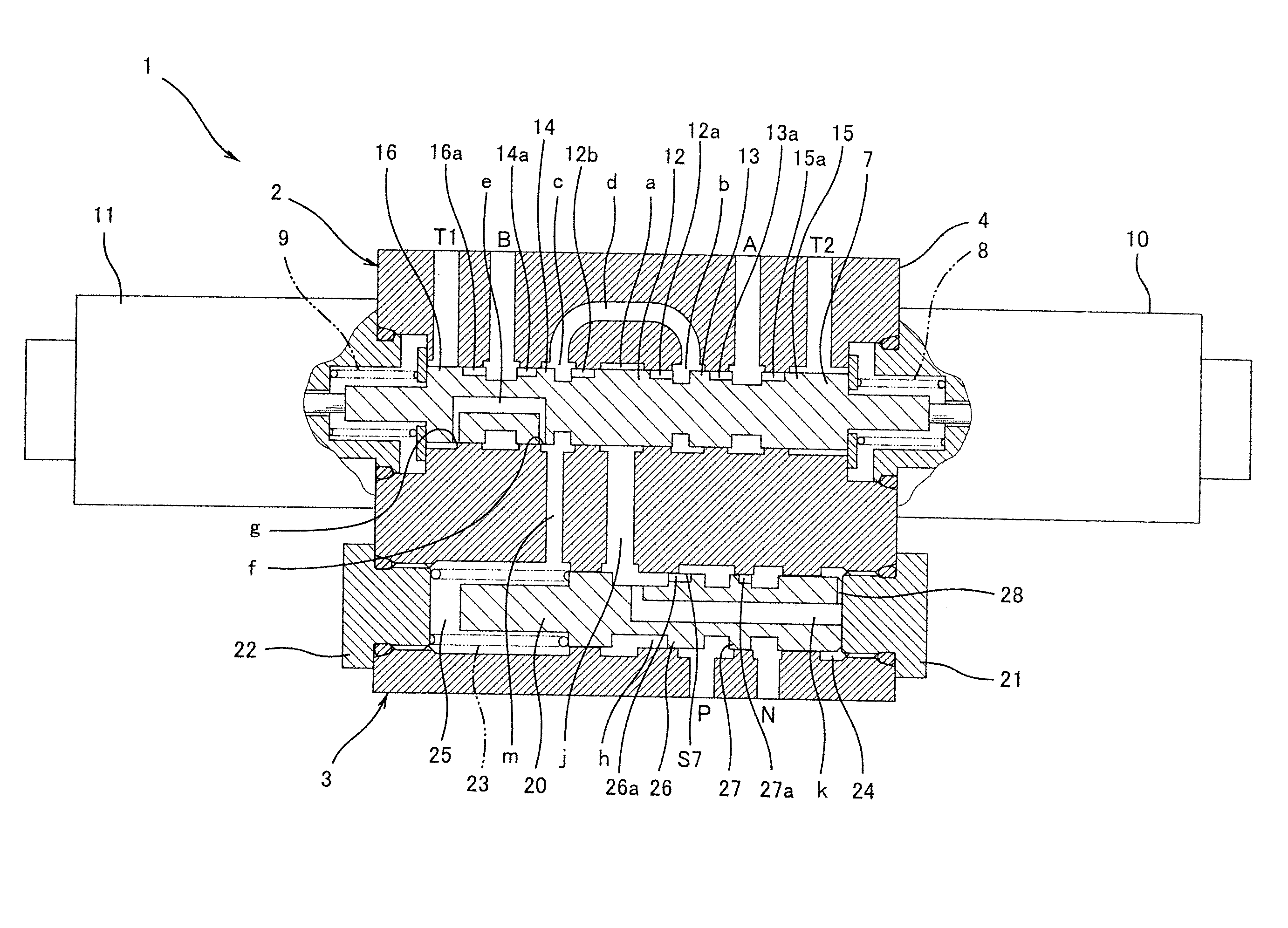
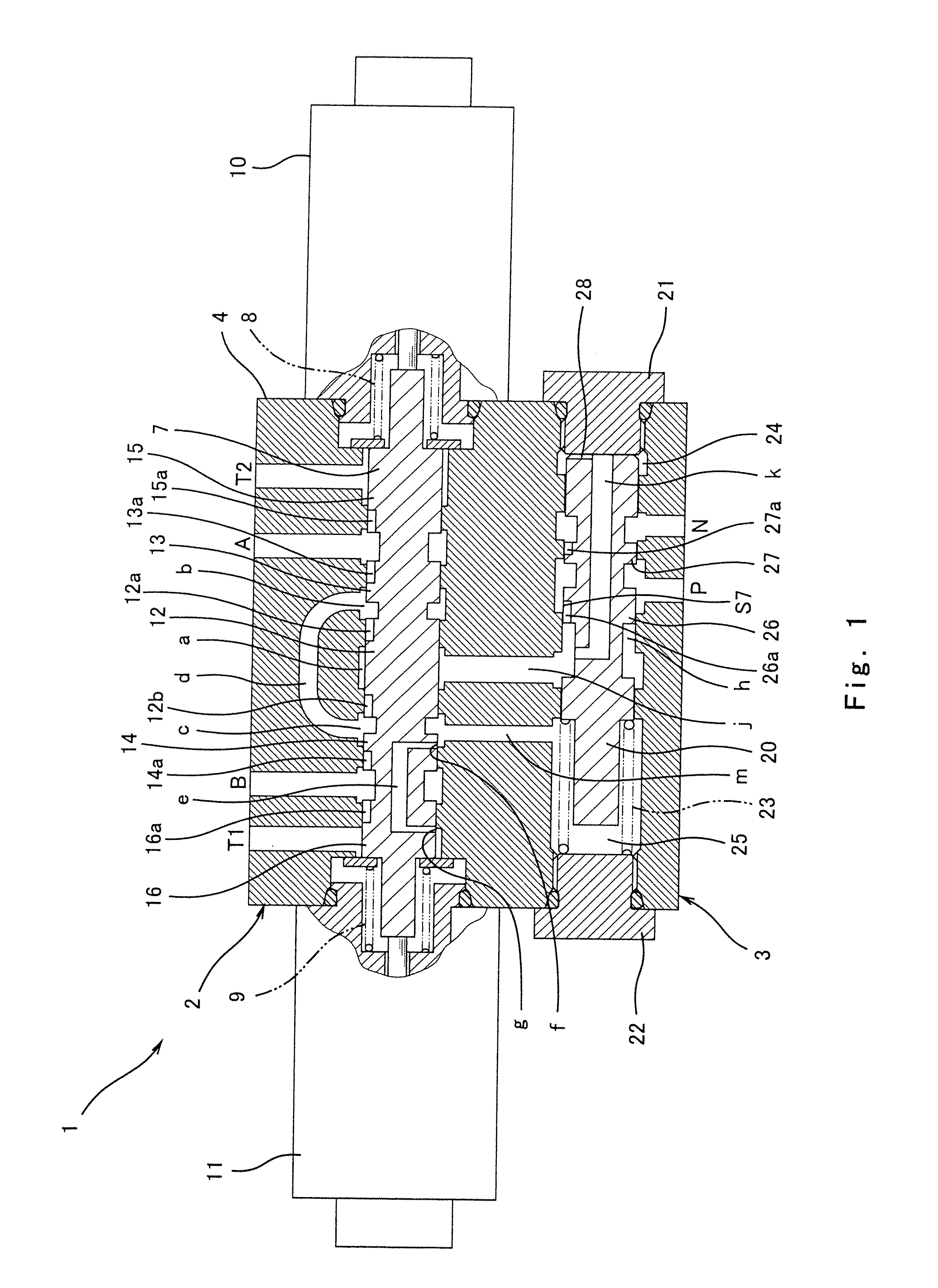
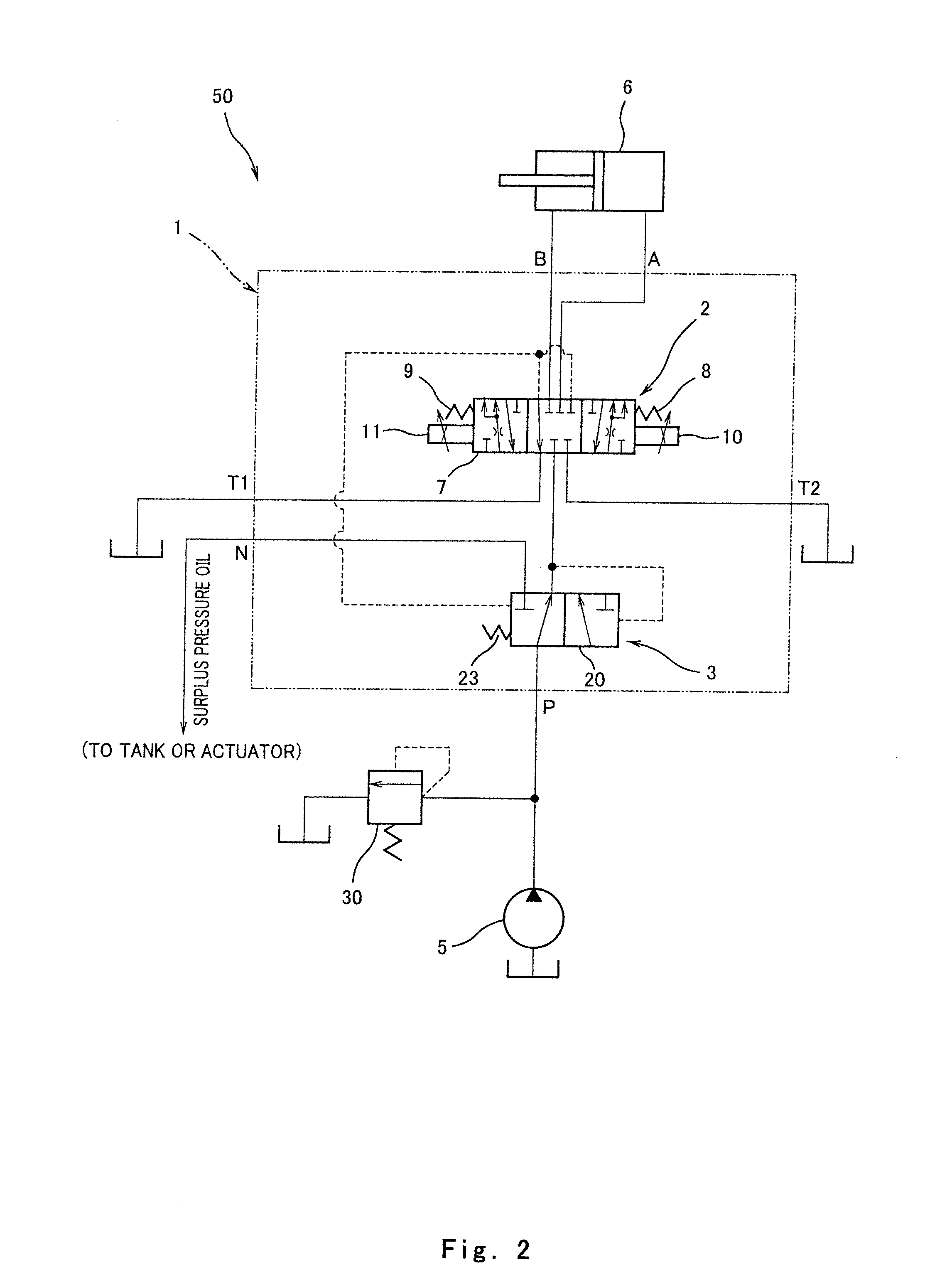
[0032]As shown in FIGS. 1 and 2, a pressure compensated electromagnetic proportional directional flow control valve 1 of Embodiment 1 integrally includes a direct operated electromagnetic proportional directional flow control valve 2 and a pressure compensated valve 3. The pressure compensated valve 3 carries out pressure compensation of a flow rate controlled by the electromagnetic proportional directional flow control valve 2. A casing 4 of the pressure compensated electromagnetic proportional directional flow control valve 1 includes an oil pressure supply port P (liquid-pressure supply port), a first external connection port A, a second external connection port B, a pair of return ports T1 and T2, and a branch port N, which are open to outside.
[0033]The oil pressure supply port P is communicated with a discharge port of an oil-pressure pump 5 (external liquid-pressure source), and the pressure oil is supplied from the oil-pressure pump 5 to the oil pressure supply port P. The fi...
embodiment 2
[0063]As shown in FIG. 5, a difference between a pressure compensated electromagnetic proportional directional flow control valve 100 of Embodiment 2 and the pressure compensated electromagnetic proportional directional flow control valve 1 of Embodiment 1 is that a pressure compensated valve 103 does not include the derivation port variable aperture S7 (see FIG. 1). Specifically, a pressure compensation spool 120 does not include the land 26 shown in FIG. 1 and is configured such that the liquid-pressure supply port P and the derivation port h are always communicated with each other. Even with such configuration, the pressure compensation function can be achieved by adjusting the flow rate of the pressure oil flowing to the branch port N by the branch port variable aperture S8. Since the flow rate of the pressure oil flowing to the introducing port a of the electromagnetic proportional directional flow control valve 2 is controlled by causing the pressure oil to always flow to the ...
embodiment 3
[0064]As shown in FIGS. 6 and 7, a difference between a pressure compensated electromagnetic proportional directional flow control valve 200 of Embodiment 3 and the pressure compensated electromagnetic proportional directional flow control valve 1 of Embodiment 1 is that the first pressure passage k formed at a pressure compensation spool 220 is also communicated with the second pressure chamber 25.
[0065]In a case where the directional flow control spool 7 is located at the neutral position, each of the external pressure introducing port b, the communication passage d, the external pressure introducing port c, the second pressure passage m, and the second pressure chamber 25 is communicated with the return port T1 through the connection passage e. Thus, the pressure of each of the above components b, d, c, m, and 25 become the tank pressure. From this state, the directional flow control spool 7 is driven to the left or the right, and at the moment that the connection passage e is cl...
PUM
 Abstract
Description
Claims
Application Information