Method of manufacturing a pipe coupling component, method of manufacutring a casing structural member, and pipe coupling sturcture for a hollow part

a manufacturing method and technology for pipe couplings, applied in the direction of hose connections, couplings, light and heating apparatus, etc., can solve the problems of difficult formation of the main body of the casing, leakage of cooling, etc., to prevent the formation of a relatively large clearance, prevent the amount of material to be removed, and prevent the effect of fluid leakag

Inactive Publication Date: 2010-12-23
SHOWA DENKO KK
View PDF2 Cites 9 Cited by
  • Summary
  • Abstract
  • Description
  • Claims
  • Application Information

AI Technical Summary

Benefits of technology

[0031]According to the method of par. 1), there can be manufactured a pipe coupling component including a semi-tubular portion which is to come into close contact with a half of the outer circumferential surface of a pipe, and flat portions which are integrally formed along opposite side edges of the semi-tubular portion and are located on a common plane, in which edge portions are formed, rather than round portions, at the boundaries between the inner circumferential surface of the semi-tubular portion and the surfaces of the flat portions facing the direction toward which the semi-tubular portion is open. Accordingly, when two pipe coupling components manufactured by this method are combined such that the openings of their semi-tubular portions face each other, it is possible to prevent formation of a relatively large clearance between the inner circumferential surface of a tubular portion formed by the two semi-tubular portions and the outer circumferential surface of the pipe inserted into the tubular portion. As a result, it is possible to prevent leakage of fluid from a product formed from the two pipe coupling components.
[0032]According to the method of par. 2), the size of the burrs of the fifth intermediate product produced in the fifth step of the above-described method of par. 1) can be set to such a size that, through removal of the burrs in the sixth step of the method, edge portions can be formed, without fail, at the boundaries between the inner circumferential surface of the semi-tubular portion and the surfaces of the flat portions facing the direction toward which the semi-tubular portion is open, and that the amount of the material to be removed can be minimized.
[0033]According to the method of par. 3), there can be produced an upper structural member including a top wall forming portion that forms the top wall of the casing main body, a circumferential wall forming portion that forms the upper half portion of the circumferential wall of the casing main body, a base portion forming portion that forms the upper half portion of the base portion of the fluid passage section, a semi-tubular coupling portion forming portion that forms the upper half portion of the pipe coupling portion of the fluid passage section, and flat portions integrally formed along opposite side edges of the coupling portion forming portion and being located on a common plane, in which edge portions are formed, rather than round portions, at the boundaries between the inner circumferential surface of the coupling portion forming portion and surfaces of the flat portions facing the direction toward which the coupling portion forming portion is open. Further, there can be produced a lower structural member including a bottom wall forming portion that forms the bottom wall of the casing main body, a circumferential wall forming portion that forms the lower half portion of the circumferential wall of the casing main body, a base portion forming portion that forms the lower half portion of the base portion of the fluid passage section, a semi-tubular coupling portion forming portion that forms the lower half portion of the pipe coupling portion of the fluid passage section, and flat portions integrally formed along opposite side edges of the coupling portion forming portion and being located on a common plane, in which edge portions are formed, rather than round portions, at the boundaries between the inner circumferential surface of the coupling portion forming portion and surfaces of the flat portions facing the direction toward which the coupling portion forming portion is open. Accordingly, when the upper and lower structural components manufactured by this method are combined such that the openings of their coupling portion forming portions face each other, it is possible to prevent formation of a relatively large clearance between the inner circumferential surface of the pipe coupling portion formed by the two coupling portion forming portions and the outer circumferential surface of the pipe inserted into the pipe coupling portion. As a result, it is possible to prevent leakage of fluid from a casing formed from the upper and lower structural members.
[0034]According to the method of par. 4), the size of the burrs of the fifth intermediate product produced in the fifth step of the above-described method of par. 3) can be set to such a size that, through removal of the burrs in the sixth step of the method, edge portions can be formed, without fail, at the boundaries between the inner circumferential surface of the coupling portion forming portion and the surfaces of the flat portions facing the direction toward which the coupling portion forming portions is open, and that the amount of the material to be removed can be minimized.
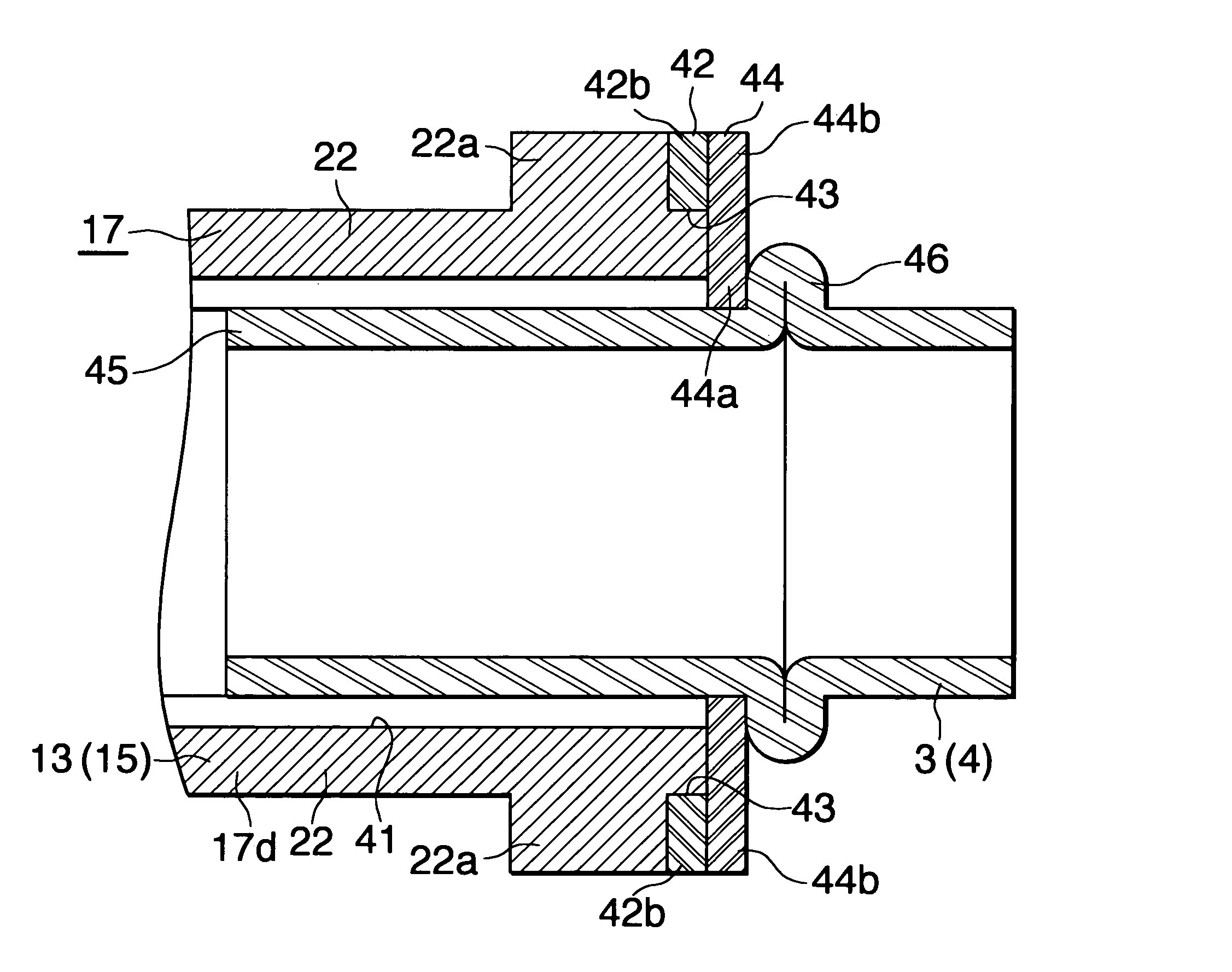
[0035]According to the pipe coupling structure of par. 5), a first outward extending flange is provided at a distal end portion of the pipe coupling portion to surround the two coupling portion forming portions; the outer circumferential edge of the first outward extending flange is located outward of the boundaries between the inner circumferential surface of each coupling portion forming portion and the surfaces of the corresponding flat portions facing a direction toward which the coupling portion forming portion is open; the pipe includes a to-be-inserted portion which is inserted into the pipe coupling portion, and a second outward extending flange provided on the outer side of the to-be-inserted portion; a coupling auxiliary member is disposed between the first outward extending flange on the hollow component side and the second outward extending flange of the pipe, and is brazed to the two outward extending flanges; and the coupling auxiliary member covers at least portions of end surfaces of the flat portions formed on the coupling portion forming portions of the pipe coupling portion, the end surfaces being located on the side toward the first outward extending flange. Therefore, even in the case where round portions are formed at the boundaries between the inner circumferential surface of each coupling portion forming portion and the surfaces of the corresponding flat portions facing the direction toward which the coupling portion forming portion is open, and, as a result, a relatively large clearance is formed between the inner circumferential surface of the tubular pipe coupling portion formed by the coupling portion forming portions and the outer circumferential surface of the pipe inserted into the pipe coupling portion, the coupling auxiliary member closes the open end of the clearance located on the side toward the first outward extending flange. Accordingly, leakage of fluid from the hollow component can be prevented.
[0036]According to the pipe coupling structure of par. 6), a first outward extending flange is provided at a distal end portion of the pipe coupling portion to surround the two coupling portion forming portions; the outer circumferential edge of the first outward extending flange is located outward of the boundaries between the inner circumferential surface of each coupling portion forming portion and the surfaces of the corresponding flat portions facing the direction toward which the coupling portion forming portion is open; the pipe includes a to-be-inserted portion which is inserted into the pipe coupling portion, and a second outward extending flange provided on the outer side of the to-be-inserted portion; the first outward extending flange and the second outward extending flange are brazed together; and the outer circumferential edge of the brazing region where the first and second outward extending flanges are brazed together is located outward of the boundaries between the inner circumferential surface of each coupling portion forming portion and the surfaces of the corresponding flat portions facing the direction toward which the coupling portion forming portion is open. Therefore, even in the case where round portions are formed at the boundaries between the inner circumferential surface of each coupling portion forming portion and the surfaces of the corresponding flat portions facing the direction toward which the coupling portion forming portion is open, and, as a result, a relatively large clearance is formed between the inner circumferential surface of the tubular pipe coupling portion formed by the coupling portion forming portions and the outer circumferential surface of the pipe inserted into the pipe coupling portion, the second outward extending flange closes the open end of the clearance located on the side toward the first outward extending flange. Accordingly, leakage of fluid from the hollow component can be prevented.

Problems solved by technology

However, the liquid-cooled-type cooling apparatus disclosed in Patent Document 1 has a problem in that the formation of the main body of the casing is difficult.
However, in this case, the following problems may occur.
Therefore, the clearances (72) are not filled with a brazing material, and a manufactured liquid-cooled-type cooling apparatus may have leakage of cooling-liquid from the casing.

Method used


Image

  • Method of manufacturing a pipe coupling component, method of manufacutring a casing structural member, and pipe coupling sturcture for a hollow part
  • Method of manufacturing a pipe coupling component, method of manufacutring a casing structural member, and pipe coupling sturcture for a hollow part
  • Method of manufacturing a pipe coupling component, method of manufacutring a casing structural member, and pipe coupling sturcture for a hollow part

Examples


embodiment 1

[0044]FIGS. 1 to 6 show the present embodiment in which the method of manufacturing a casing structural member according to the present invention is applied to manufacture of casing structural members of a liquid-cooled-type cooling apparatus.

[0045]FIGS. 1 to 4 show a liquid-cooled-type cooling apparatus which includes a casing composed of structural members manufactured by the method of the present invention. FIGS. 5 and 6 show a method of manufacturing the structural members of the casing.

[0046]Notably, in the description of the liquid-cooled-type cooling apparatus based on FIGS. 1 to 4, the lower side of FIG. 2 will be referred to as the front, and the upper side of FIG. 2 will be referred to as the rear; and the upper, lower, left-hand, and right-hand sides of FIG. 3 will be referred to as “upper,”“lower,”“left,” and “right,” respectively.

[0047]In FIGS. 1 to 3, a liquid-cooled-type cooling apparatus (1) comprises a hollow casing (2); an inflow pipe (3) formed of a round pipe and...

embodiment 2

[0064]FIGS. 7 to 13 show this embodiment in which the structure for coupling a pipe to a hollow component according to the present invention is applied to coupling of inflow and outflow pipes to pipe coupling portions of a casing of a liquid-cooled-type cooling apparatus.

[0065]FIGS. 7 to 11 show a liquid-cooled-type cooling apparatus having a casing to which pipes are connected by use of the pipe coupling structure of the present invention. FIGS. 12 to 13 show a method of coupling the pipes to the casing.

[0066]Notably, in the description, the lower side of FIG. 8 will be referred to as the front, and the upper side of FIG. 8 will be referred to as the rear; and the upper, lower, left-hand, and right-hand sides of FIG. 9 will be referred to as “upper,”“lower,”“left,” and “right,” respectively.

[0067]In FIGS. 7 to 9, each of the upper and lower structural members (16) (17) of the liquid-cooled-type cooling apparatus (1) is formed through press work performed on an aluminum brazing shee...

embodiment 3

[0074]FIGS. 14 to 16 show the present embodiment in which the structure for coupling a pipe to a hollow component according to the present invention is applied to connection of inflow and outflow pipes to pipe coupling portions of a casing of a liquid-cooled-type cooling apparatus.

[0075]In the case of the structure according to the present embodiment for coupling the inflow pipe (3) and the outflow pipe (4) to the pipe coupling portions (13) (15) of the casing (2), a first outward extending flange (50) is provided at the distal end portion of the pipe coupling portion (13) (15) so that the flange surrounds the coupling portion forming portions (16d) (17d) and the horizontal flat portions (21) (22) of the upper and lower structural members (16) (17). The outer circumferential edge of the annular portion (50a) of the first outward extending flange (50) is located radially outward of the round portions (40) formed at the boundaries between the inner circumferential surface of the coupl...


PUM

PropertyMeasurementUnit
inclination angleaaaaaaaaaa
widthaaaaaaaaaa
depthaaaaaaaaaa

Abstract

In a first step of this method, a first intermediate product 42 having a coupling portion forming portion 16d and flat portions 21 is produced. In a second step, there is produced a second intermediate product 44 which is larger in the bending depth of the coupling portion forming portion 16d and is smaller in width of the flat portions 21 than the first intermediate product 42. In a third step, a third intermediate product 36 having the coupling portion forming portion 16d, sloping flat portions 34, and narrow flat portions 35 is produced. In a fourth step, the sloping flat portions 34 of the third intermediate product 36 are pressed obliquely upward so as to cause the material to move to the boundaries between the sloping flat portions 35 and the side walls of the coupling portion forming portion 16d, to thereby produce a fourth intermediate product 37. In a fifth step, the side walls of the coupling portion forming portion 16d, the sloping flat portions 34 and the narrow flat portions 35 of the fourth intermediate product 37 are pressed from the upper and lower sides, to thereby form a fifth intermediate product 39 in which burrs 38 are formed at the opening-side end portions of the side walls of the coupling portion forming portion 16d. In a sixth step, the burrs 38 are removed, whereby a casing structural member 16 produced. This method enables manufacture of casing structural members which can prevent leakage of fluid.

Description

TECHNICAL FIELD[0001]The present invention relates to a method of manufacturing a pipe coupling component used in a liquid-cooled-type cooling device for cooling a heat-generating body composed of an electronic component such as a semiconductor device, and to a method of manufacturing a casing structural member of the cooling device.BACKGROUND ART[0002]A conventionally known liquid-cooled-type cooling apparatus for cooling an electronic component comprises a casing composed of a top wall, a bottom wall, and a circumferential wall; a tube disposed in the casing; and inlet and outlet pipes connected to the circumferential wall of the casing, wherein the casing is composed of a box-shaped main body that opens upward and forms the bottom wall and the circumferential wall, and a lid for closing the opening of the main body; through holes are formed in the circumferential wall of the main body; and end portions of the inlet and outlet pipes are inserted into the through holes, and are bra...

Claims


Application Information

Patent Timeline
Patent Type & Authority Applications(United States)
IPC IPC(8): F16L25/00B23P17/00
CPCB21D39/04B21D39/06F16L37/1225F28F3/025F28F3/12Y10T29/49428F28F9/0248H01L23/473H01L2924/0002F28F9/0246H01L2924/00
Inventor UNENO, DAISUKE
Owner SHOWA DENKO KK
Why Eureka
Try Eureka