Method of controlling a gear pump as well as an application of the method

a gear pump and gear arrangement technology, applied in the direction of rotary or oscillating piston engines, engine lubrication, rotary piston engines, etc., can solve the problems of tooth flank wear, damage to the tooth flanks through abrasion or wear, and significant wear, especially when conveying abrasive media

Active Publication Date: 2010-12-23
MAAG PUMP SYST TEXTRON
View PDF8 Cites 47 Cited by
  • Summary
  • Abstract
  • Description
  • Claims
  • Application Information

AI Technical Summary

Benefits of technology

[0040]The advantage associate with this is that no disturbing pulsation is present at the d

Problems solved by technology

Often problems of wear occur at the tooth flanks through excessive contact pressure due to the torque transmission.
Damages on the tooth flanks can occur through abrasion or wear (pittings, micro-weldings, abrasion), especially in the manufacturing of polymers in large polymerization installations or in compounding of plastics with large throughputs at very high backpressures and high temperatures, i.e. overall high torque.
It has been shown that in known ge

Method used


Image

  • Method of controlling a gear pump as well as an application of the method
  • Method of controlling a gear pump as well as an application of the method
  • Method of controlling a gear pump as well as an application of the method

Examples


Embodiment Construction

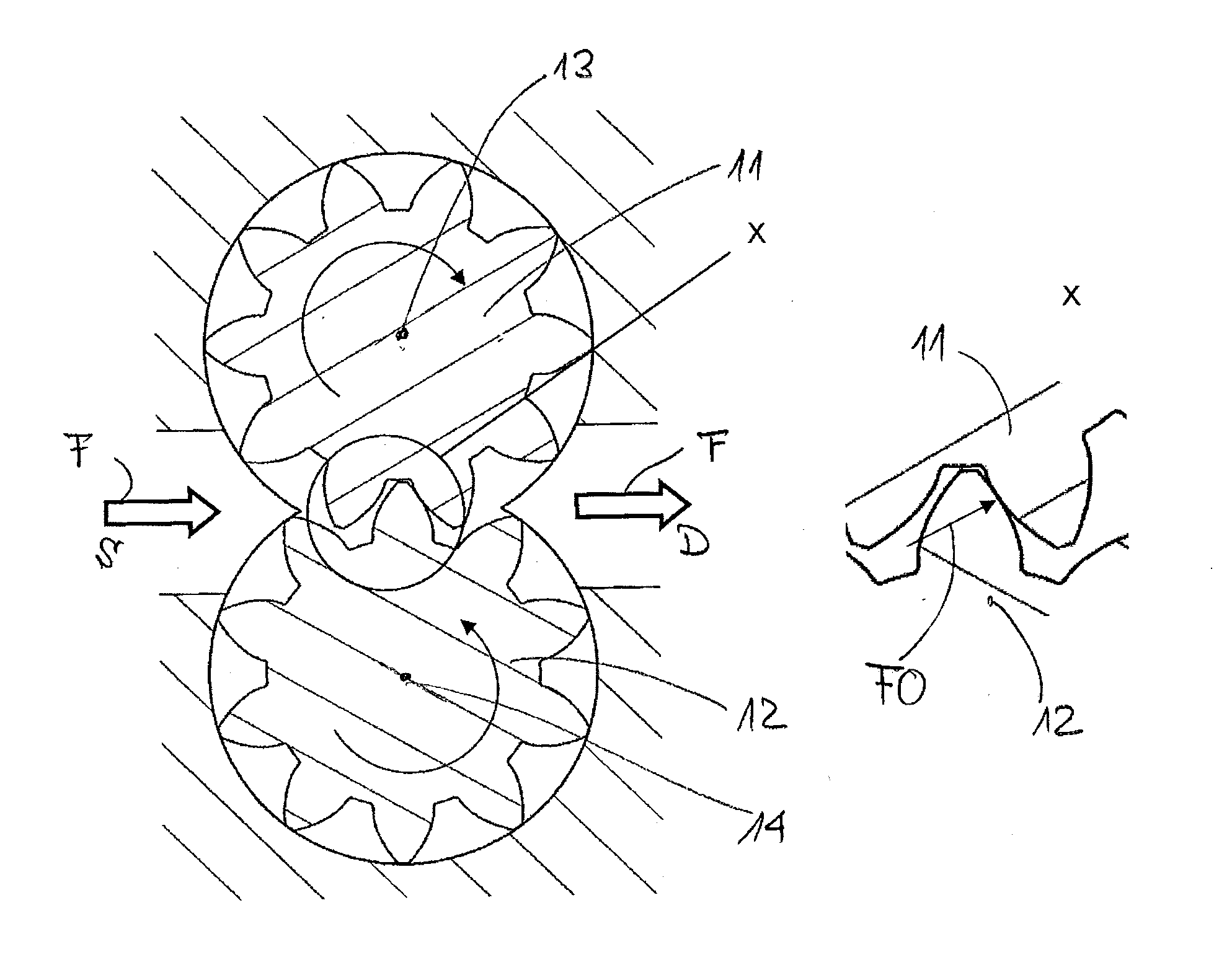
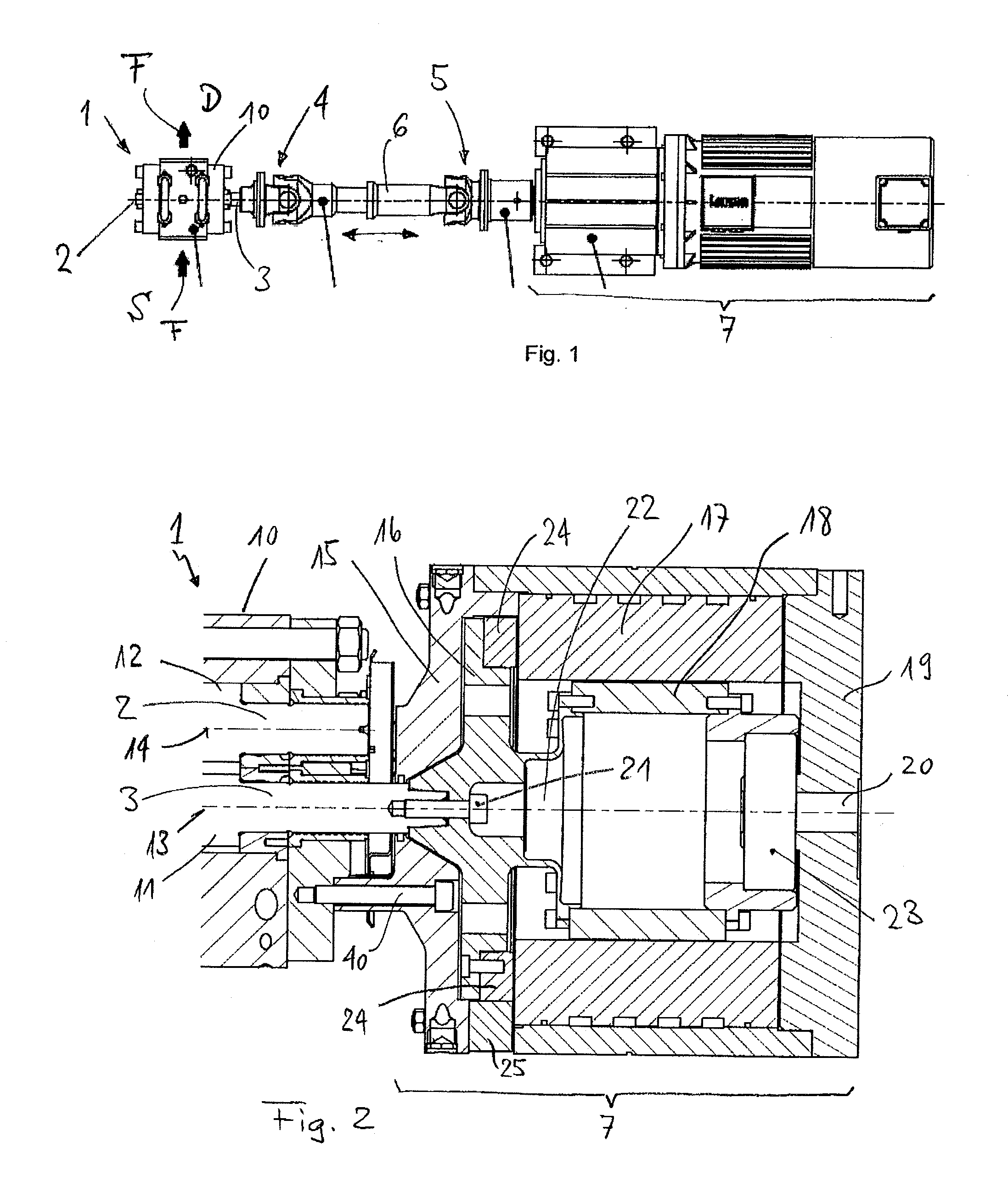
[0067]In FIG. 1 a known arrangement including a gear pump 1 is shown which conveys a medium F to be conveyed from a suction side S to a discharge side D. A pump housing 10 can be seen in FIG. 1 through which two shafts 2 and 3 extend to the outside. The shaft 3 extending to the outside is connected to a drive unit 7 via a first universal joint 4, an axle segment 6 whose length is adjustable and a second universal joint 5. Accordingly, also the shaft 2 extending to the outside is connected to a further drive unit (not shown in FIG. 1) via a corresponding first and second universal joint as well as via a corresponding axle segment. Thus, the gear wheels (not visible in FIG. 1) are each propelled by an own drive unit.

[0068]It should be noted that the double universal joint consisting of the first and the second universal joint 4 and 5 together with the adjustable axle segment 6 is provided to accommodate lateral and angular deviations of the drive unit in relation to the shafts 2 or 3....


PUM


Abstract

A method of controlling a gear pump comprising two meshing gear wheels (11, 12), wherein the two gear wheels (11, 12) are driven via respective shafts (2, 3) each by a drive unit (7, 8). A current position of the one gear wheel (11, 12) is determined with respect to the current position of the other gear wheel (12, 11), and the current position of the one gear wheel (11, 12) is continuously adjusted with respect to the current position of the other gear wheel (12, 11) according to specified predefined operating conditions.

Description

TECHNICAL FIELD [0001]The present invention relates to a method and an arrangement for controlling a gear pump comprising two meshing gear wheels, wherein the two gear wheels are driven via respective shafts each by a drive unit.BACKGROUND AND SUMMARY [0002]Gear pumps consist of two meshing gear wheels which are mounted on shafts, wherein generally one shaft is connected to a drive unit. The shaft which is not being driven by a drive unit is driven by torque transmission from the shaft being driven via the tooth flanks.[0003]Often problems of wear occur at the tooth flanks through excessive contact pressure due to the torque transmission. Namely, on the one hand because the pressure load brought about by the pressure difference needs to be transferred via the tooth flanks from the shaft being driven to the driven shaft, and on the other hand because the friction needs to be overcome. Damages on the tooth flanks can occur through abrasion or wear (pittings, micro-weldings, abrasion),...

Claims


Application Information

Patent Timeline
IPC IPC(8): F04C28/00F03C2/08F04C2/18
CPCF04C2/18F04C2240/402F04C14/08
Inventor AREGGER, MARKUS
Owner MAAG PUMP SYST TEXTRON
Why Eureka
Try Eureka