Pedicle screw with expansion anchor sleeve

Inactive Publication Date: 2010-12-23
DAVIS REGINALD J
View PDF3 Cites 150 Cited by
  • Summary
  • Abstract
  • Description
  • Claims
  • Application Information

AI Technical Summary

Benefits of technology

[0014]It is another object to provide a bone anchor that does not rely on the engagement of the threads of a screw with the exposed bone surfaces of a hole drilled in the vertebra of a patient for its strength and ability to remain fixed in place.
[0015]It is another object to provide a bone anchor that allows insertion and facilitates introduction of ancillary elements such as bone grafts and/or medicament-leaching graft promoters.
[0016]In accordance with the foregoing objects, the present invention is a bone anchor for use in conjunction with orthopedic spinal fixation comprising an elongate screw anchor having a shank extending to a threaded proximal tip for threaded insertion into a hole prepared into a vertebral body through the pedicle of the vertebra from the posterior approach. The shank of the anchor is of smaller diameter than the proximal tip so as to receive a sleeve after insertion into the bone. T

Problems solved by technology

Genetic or developmental irregularities, trauma, disease or other causes can result in spinal pathologies which degrade the spinal structures limiting the range of motion, endangering the neural elements housed within the spinal column and causing tremendous pain to the individual.
In many cases surgical intervention is required after non-invasive methods have been ineffective.
A common mode of failure and a primary concern of surgeons performing spinal implantation is screw pull-out in which the surface of the bone in the whole that is engaged by the screw threads fails.
Screw pull-out is often due to the high stress imposed on the assembly by the relative motion of the spine in everyday use but

Method used


Image

  • Pedicle screw with expansion anchor sleeve
  • Pedicle screw with expansion anchor sleeve
  • Pedicle screw with expansion anchor sleeve

Examples


Example

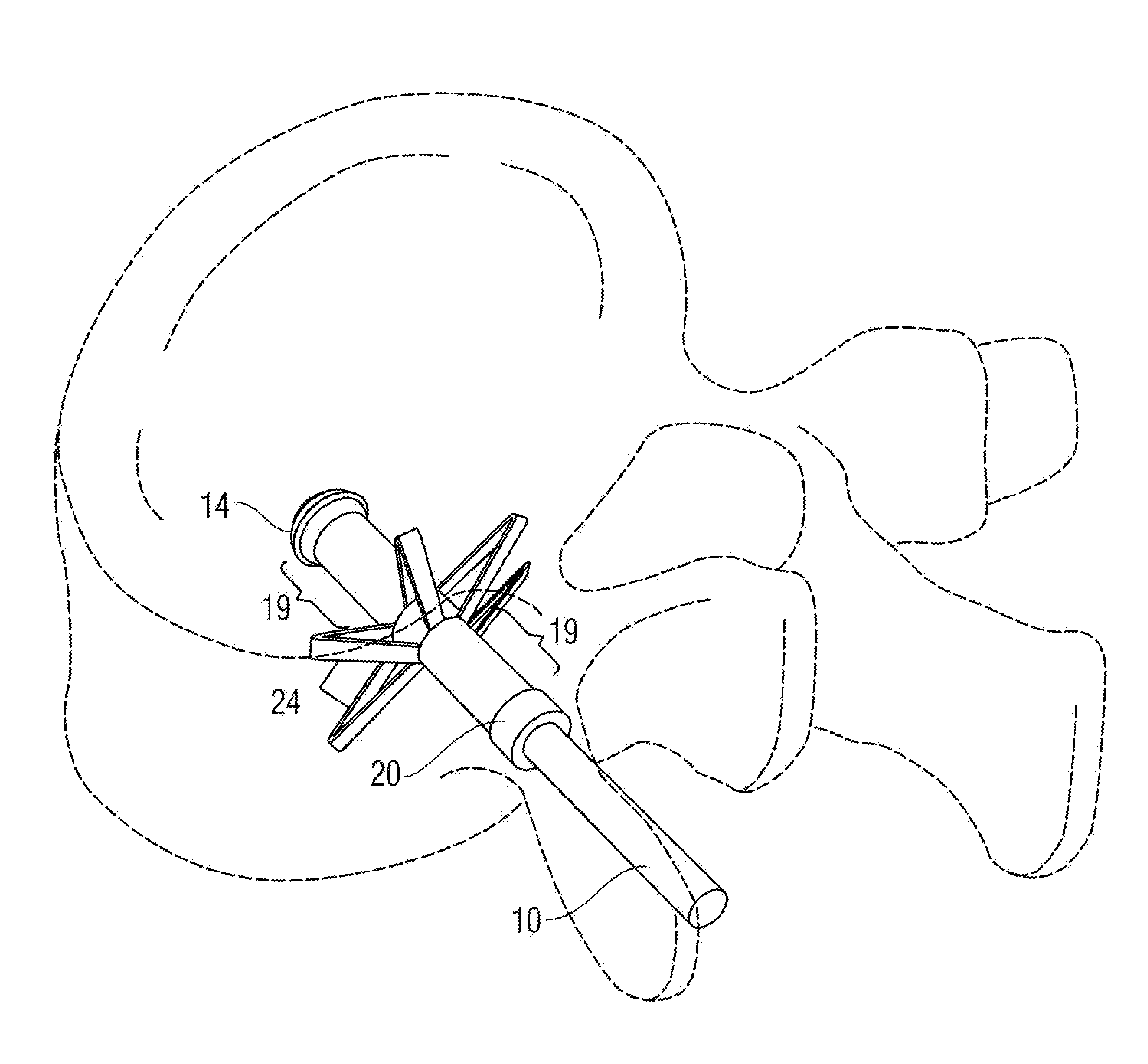
[0023]The present invention is a modular bone anchor in the form of a pedicle screw for insertion into the vertebral body of a spinal vertebra via the pedicle. The bone anchor of the present invention may be inserted into a relatively small hole made through the cortical shell of the vertebra and into the vertebral body via the pedicle and thereafter compressed so as to expand in diameter for secure and selectively permanent engagement with the vertebra.

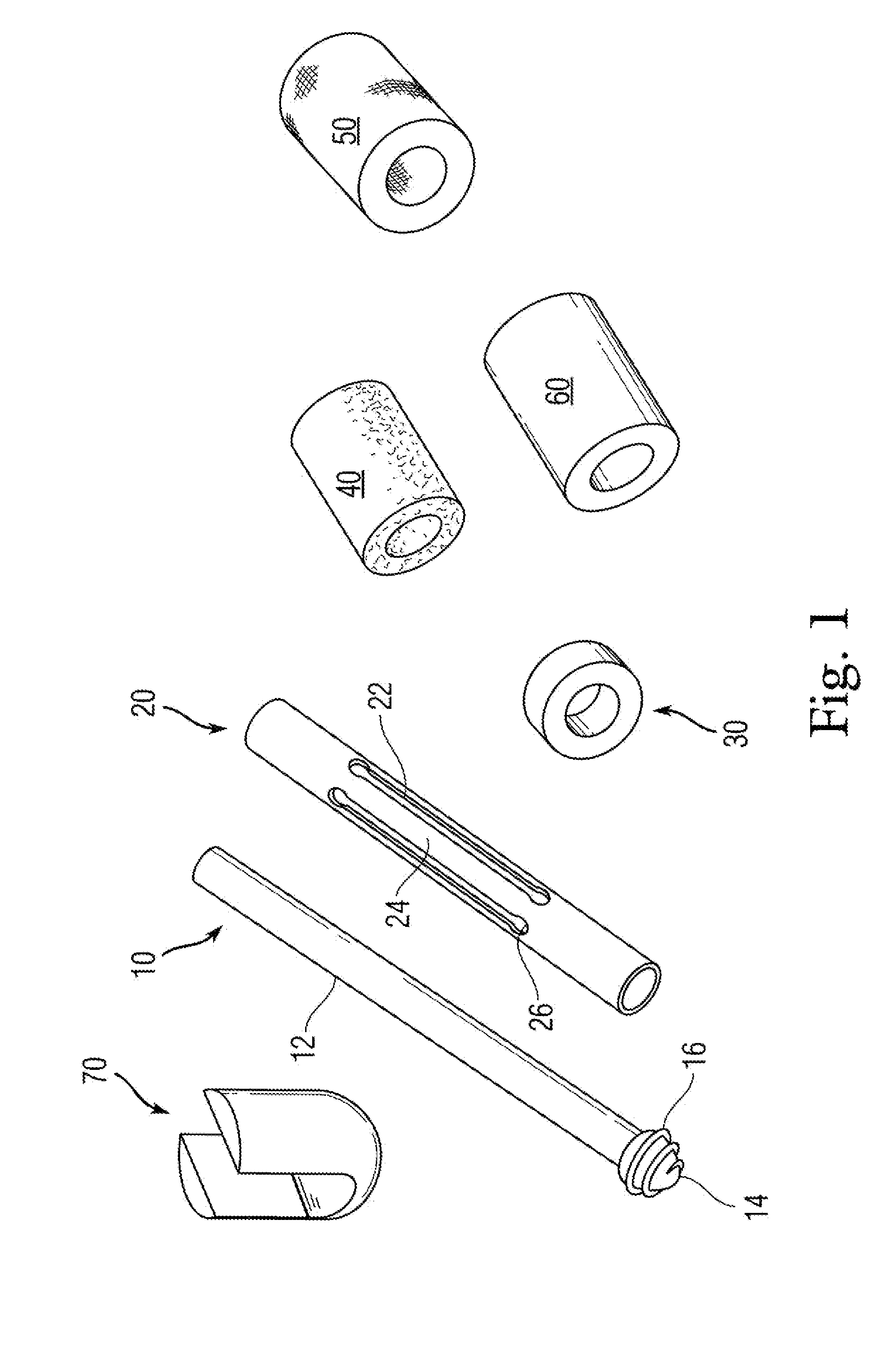
[0024]FIG. 1 is an exploded view of the elements of an embodiment of the invention prior to assembly and surgical insertion. Basic screw 10 is an elongate shaft preferably round in cross section, and from 30 mm to 60 mm long (up to 2½ inches). Basic screw 10 has a shank 12 of constant diameter substantially along its entire length all the way to one end.

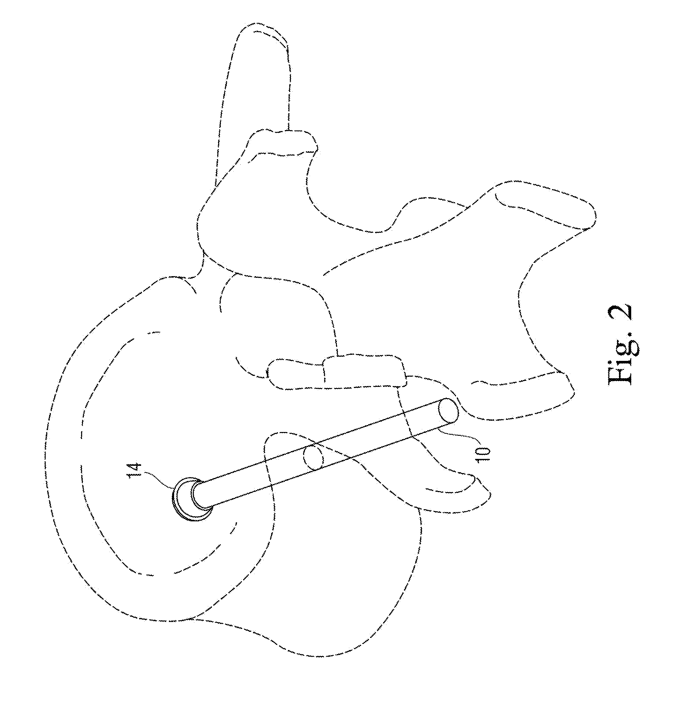
[0025]As seen in FIG. 2, the other end is provided with a proximal tip 14 for insertion into a predrilled hole through the cortical bone of the vertebral pedicle and into the cancello...


PUM


Abstract

A bone anchor for use in conjunction with orthopedic spinal fixation comprising a pedicle screw having a threaded proximal tip for threaded insertion into a hole prepared into a vertebral body through the pedicle of the vertebra from the posterior approach. The shank of the anchor is of smaller diameter than the proximal tip so as to receive a sleeve after insertion into the bone. The tubular sleeve is provided with a plurality of longitudinal slots evenly arranged about the longitudinal axis of the sleeve to forming a plurality of longitudinal. A tubular compression collar for insertion over said shank portion is provided on the shank and driven toward the proximal tip compression the sleeve and causing the ribs to expand radially into a star pattern securing the anchor in the bone. A tubular collar of natural or synthetic bone growth promoting material may be inserted to promote bone growth, close the hole and further stabilize the anchor. An elastomeric collar may also be inserted over the shank and extend beyond the end of the shank to flexibly receive a rod seat for receiving an orthopedic rod affixed to said elastomeric collar.

Description

CROSS-REFERENCE TO RELATED APPLICATIONS[0001]This application claims the benefit of U.S. Provisional Application No. 61 / 269,274 for “PEDICLE SCREW WITH EXPANSION ANCHOR SLEEVE,” filed Jun. 23, 2009, which is incorporated by reference.BACKGROUND OF THE INVENTION[0002]1. Field of the Invention[0003]The present invention relates to spinal fixation devices and, more particularly to a modular screw / sleeve assembly for insertion into spinal bone for fixation of the vertebra such as by affixing orthopedic implantation structures to the spine.[0004]2. Description of the Background[0005]The spinal column is a highly complex arrangement of 24 individual vertebral bones separated by cartilaginous intervertebral discs supported by muscle and ligament that houses and protects critical elements of the nervous system and supports the body. Despite this role the spine is a highly flexible structure that is capable of significant articulation through a wide range of motion. In a healthy spine this f...

Claims


Application Information

Patent Timeline
IPC IPC(8): A61B17/86
CPCA61B17/7032A61B17/8685A61B17/864A61B17/8625
Inventor DAVIS, REGINALD J.
Owner DAVIS REGINALD J
Why Eureka
Try Eureka