Methodology and apparatus to terminate abandoned active implantable medical device leads

a technology of active implantable medical devices and methods, applied in the field of energy induced onto abandoned implanted leads, can solve the problem of energy still residing in the lead system

Inactive Publication Date: 2010-12-23
WILSON GREATBATCH LTD
View PDF14 Cites 30 Cited by
  • Summary
  • Abstract
  • Description
  • Claims
  • Application Information

AI Technical Summary

Benefits of technology

[0028]The novel abandoned lead cap of the present invention works best when bandstop filters are installed at or near the distal electrode of an implanted lead, wherein the RF energy induced by the MRI pulse field is attenuated from flowing into body tissues and thereby being dissipated. However, when bandstop filters are used, that energy still resides in the lead system. In other words, by preventing this induced energy from flowing to sensitive tissues at distal electrode interfaces, a great deal has been accomplished; however, it is still important to carefully dissipate the remaining energy that's trapped in the lead system. For abandoned leads, the most efficient way to do this is to use the metallic housing of the novel abandoned lead cap of the present invention.
[0031]The present invention additionally resides in an overall energy management system capable of controlling the energy induced in abandoned implanted leads from the RF pulsed field of MRI scanners. More particularly, the present invention resides in a tuned energy balanced system for minimizing heating of an abandoned implanted lead in a high power electromagnetic field environment. The tuned energy balanced system of the present invention comprises an abandoned implanted lead having impedance characteristics at a selected RF frequency or frequency band, an energy dissipating surface associated with the abandoned lead cap, and an energy diversion circuit conductively coupling the implanted lead to the energy dissipating surface of the abandoned lead cap. The energy diversion circuit comprises one or more passive electronic network components whose impedance characteristics can be partially tuned to the implanted lead's impedance characteristics, to facilitate transfer to the energy dissipating surface of high frequency energy induced on the implanted lead at the selected RF frequency or frequency band.

Problems solved by technology

However, when bandstop filters are used, that energy still resides in the lead system.

Method used


Image

  • Methodology and apparatus to terminate abandoned active implantable medical device leads
  • Methodology and apparatus to terminate abandoned active implantable medical device leads
  • Methodology and apparatus to terminate abandoned active implantable medical device leads

Examples


Embodiment Construction

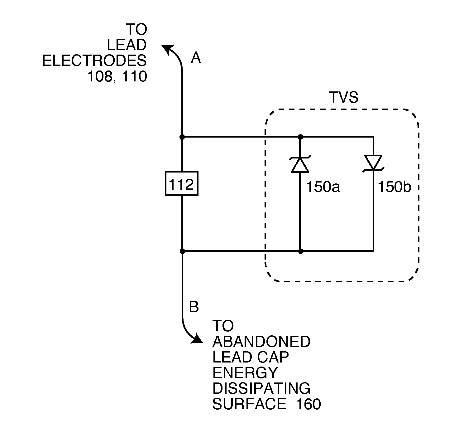
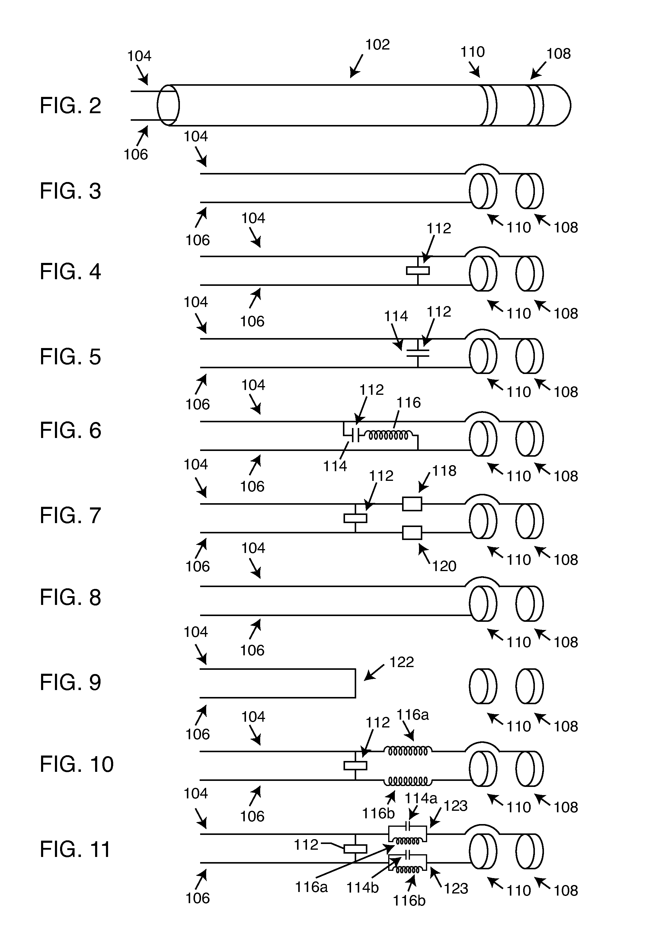
[0121]As shown in the drawings for purposes of illustration, the present invention relates to a system for terminating abandoned implanted leads to minimize heating in high power electromagnetic field environments. In a broad sense, the present invention comprises an implanted abandoned lead having impedance characteristics at a selected RF frequency or frequency band, an energy dissipating surface associated with the abandoned lead, and an energy diversion circuit conductively coupling the abandoned lead to the energy dissipating surface. The energy diversion circuit may comprise one or more passive electronic network components whose impedance characteristics are at least partially tuned to the abandoned lead's impedance characteristics, to facilitate transfer to the energy dissipating surface of high frequency energy induced on the abandoned lead at the selected RF frequency or frequency band. Certain implanted leads may have a characteristic impedance that includes capacitive re...


PUM


Abstract

An energy management system facilitates the transfer of high frequency energy coupled into an implanted abandoned lead at a selected RF frequency or frequency band, to an energy dissipating surface. This is accomplished by conductively coupling the implanted abandoned lead to the energy dissipating surface of an abandoned lead cap through an energy diversion circuit including one or more passive electronic network components whose impedance characteristics are at least partially tuned to the implanted abandoned lead's impedance characteristics.

Description

BACKGROUND OF THE INVENTION[0001]This invention generally relates to the problem of energy induced onto abandoned implanted leads during medical diagnostic procedures such as magnetic resonant imaging (MRI). Specifically, the radio frequency (RF) pulsed field of MRI can couple to an implanted lead in such a way that electromagnetic forces (EMFs) are induced in the lead. The amount of energy that is induced is related to a number of complex factors, but in general, is dependent upon the local electric field that is tangent to lead and the integral of the electric field strength along the lead. In certain situations, these EMFs can cause currents to flow into distal electrodes or in the electrode interface with body tissue. It has been documented that when this current becomes excessive, that overheating of said lead or its associated electrode or overheating of the associated interface with body tissue can occur. There have been cases of damage to such body tissue which has resulted ...

Claims


Application Information

Patent Timeline
Patent Type & Authority Applications(United States)
IPC IPC(8): A61N1/05
CPCA61B5/042A61B5/055A61B2018/00839A61B2019/448G01R33/285A61N1/05A61N1/3718A61N2001/086B82Y30/00A61B2019/5236A61B90/98A61B2090/374A61N1/086A61B5/283
Inventor STEVENSON, ROBERT A.TRUEX, BUEHL E.MUFFOLETTO, BARRY C.DABNEY, WARREN S.FRYSZ, CHRISTINE A.WILLIAMS, CHRISTOPHER MICHAELMOSCHIANO, HOLLY NOELLEFLEIGLE, JEFFKONDABATNI, KISHORE KUMARBRENDEL, RICHARD L.JOHNSON, ROBERT SHAWNBRAINARD, SCOTTHALPERIN, HENRY R.LARDO, ALBERT C.
Owner WILSON GREATBATCH LTD
Why Eureka
Try Eureka