Vibrating device and image equipment having the same

a technology which is applied in the field of vibration device and image equipment having the same, can solve the problems of dust, dust may likely enter, and make a great problem

Active Publication Date: 2010-12-30
OM DIGITAL SOLUTIONS CORP
View PDF5 Cites 24 Cited by
  • Summary
  • Abstract
  • Description
  • Claims
  • Application Information

AI Technical Summary

Benefits of technology

[0013]a support member configured to support the dust-screening member, thereby to render the back surface of the dust-screening member airtight;
[0019]a support member configured to support the dust-screening member, thereby to render the back surface of the dust-screening member airtight;

Problems solved by technology

This makes a great problem.
As these mechanisms operate, they produce dust, which may adhere to the surface of the image sensor element as well.
In such a projector, dust may likely enter the main unit of the projector from a position near the mechanism of the cooling fan.
The dust particles at these nodes cannot be removed, because the amplitude of vibration at the nodes is small.

Method used


Image

  • Vibrating device and image equipment having the same
  • Vibrating device and image equipment having the same
  • Vibrating device and image equipment having the same

Examples


first embodiment

[0057]An image equipment according to this invention, which will be exemplified below in detail, has a dust removal mechanism for the image sensor element unit that performs photoelectric conversion to produce an image signal. Here, a technique of improving the dust removal function of, for example, an electronic camera (hereinafter called “camera” will be explained. The first embodiment will be described, particularly in connection with a lens-exchangeable, single-lens reflex electronic camera (digital camera), with reference to FIGS. 1 to 2B.

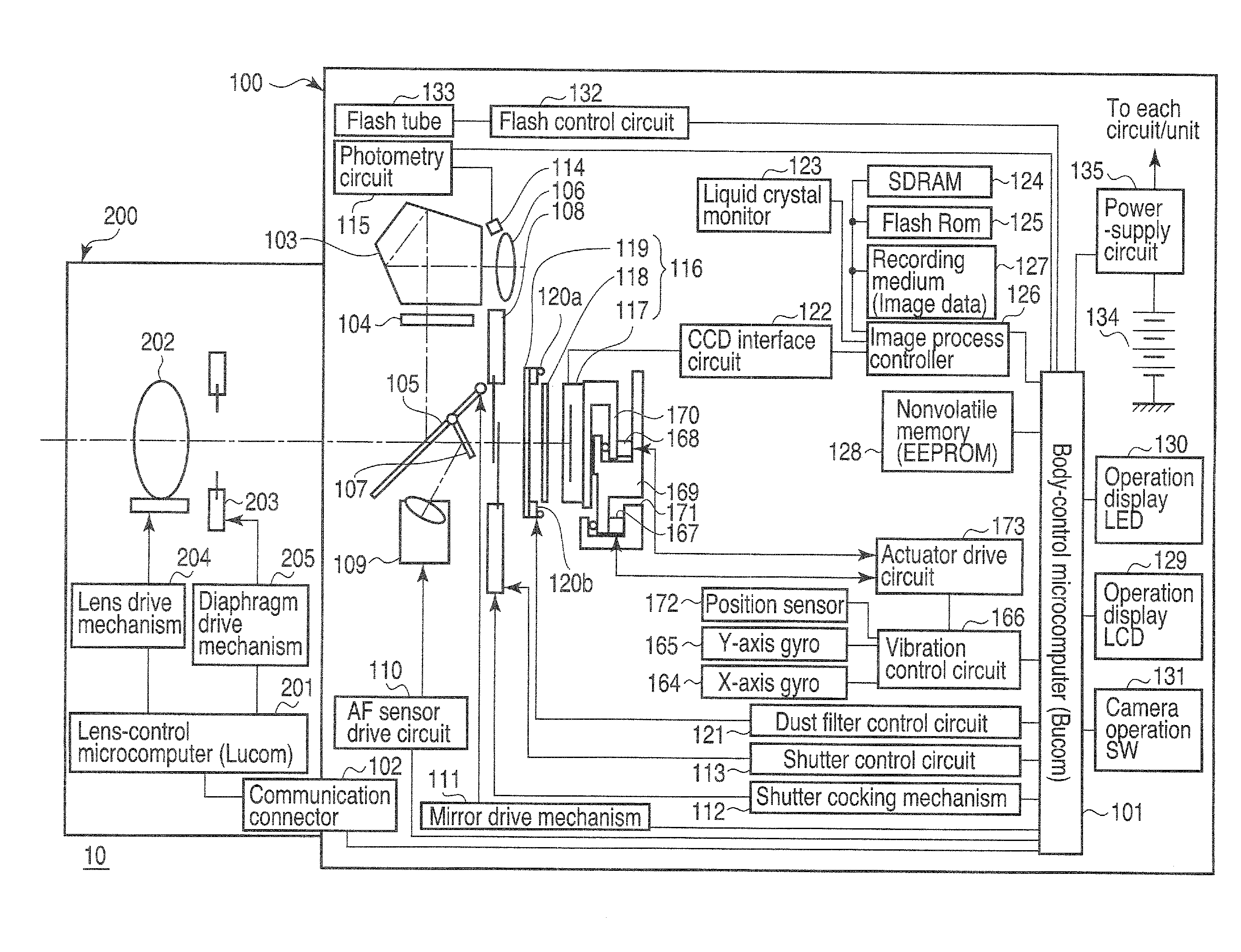
[0058]First, the system configuration of a digital camera 10 according to this embodiment will be described with reference to FIG. 1. The digital camera 10 has a system configuration that comprises body unit 100 used as camera body, and a lens unit 200 used as an exchange lens, i.e., one of accessory devices. The lens unit 200 can be attached to and detached from the body unit 100 via a lens mount (not shown) provided on the front of the body ...

second embodiment

[0168]The subroutine “silent vibration” called in the camera sequence (main routine) that the Bucom performs in a digital camera that is a second embodiment of the image equipment according to this invention will be described with reference to FIG. 19. FIG. 19 illustrates a modification of the subroutine “silent vibration” shown in FIG. 15. The second embodiment differs from the first embodiment in the operating mode of the dust filter 119. In the first embodiment, the dust filter 119 is driven at a fixed frequency, i.e., frequency f0, producing a standing wave. By contrast, in the second embodiment, the drive frequency is gradually changed, thereby achieving large-amplitude vibration at various frequencies including the resonance frequency, without strictly controlling the drive frequency.

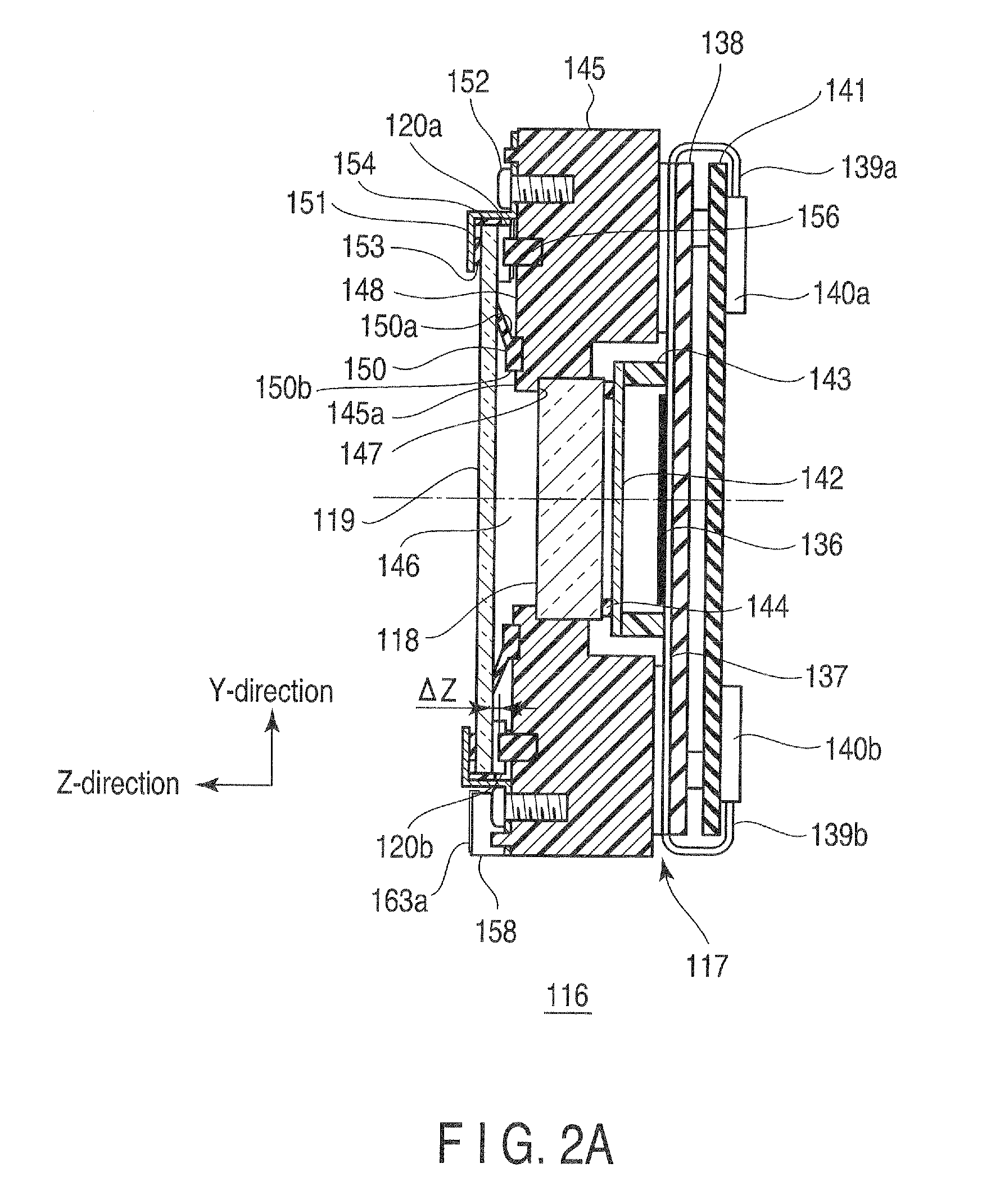
[0169]If the aspect ratio shown in FIG. 6 has changed from the design value of 0.9, during the manufacture, the vibrational mode will greatly change (that is, the vibration speed ratio will abrupt...


PUM


Abstract

A vibration control unit inputs an electrical signal to a vibrating member to generate, in a light-transmitting region of a dust-screening member, vibration forming a plurality of ridges of peaks defining a closed loop around a virtual intersection at which a virtual vibrational axis passing the half-length point of the vibrating member intersects with a virtual vibrational axis passing the half-length point of the dust-screening member. For example, the vibration is vibration whose peak including the virtual intersection gradually increases in terms of amplitude as the amplitude of the peak approaches the virtual intersection, and becomes the largest in terms of amplitude at the virtual intersection. The dust-screening member and the vibrating member have the following relation: 1.2≦Ts / Tg≦1.6, where Tg is the thickness of the thickness of the dust-screening member, and Ts is the thickness of the vibrating member.

Description

CROSS-REFERENCE TO RELATED APPLICATIONS[0001]This application is based upon and claims the benefit of priority from prior Japanese Patent Application No. 2009-155909, filed Jun. 30, 2009, the entire contents of which are incorporated herein by reference.BACKGROUND OF THE INVENTION[0002]1. Field of the Invention[0003]The present invention relates to image equipment having image forming elements such as an image sensor element or a display element, and also to a vibrating device designed to vibrate the dust-screening member that is arranged at the front of each image forming element of such an image equipment.[0004]2. Description of the Related Art[0005]As image equipment having image forming elements, there is known an image acquisition apparatus that has an image sensor element configured to produce a video signal corresponding to the light applied to its photoelectric conversion surface. Also known is an image projector that has a display element, such as liquid crystal element, wh...

Claims


Application Information

Patent Timeline
Patent Type & Authority Applications(United States)
IPC IPC(8): F28G7/00
CPCG02B27/0006H04N5/23248H04N5/2254H04N5/2171H04N23/811H04N23/52H04N23/60H04N23/68G03B17/02
Inventor KAWAI, SUMIO
Owner OM DIGITAL SOLUTIONS CORP
Why Eureka
Try Eureka