Dehumidifier for Use in Water Damage Restoration

a dehumidifier and water damage technology, applied in the field of dehumidifiers, can solve problems such as unfavorable operation, and achieve the effect of maximum performan

Inactive Publication Date: 2010-12-30
KARCHER NORTH AMERICA INC
View PDF74 Cites 27 Cited by
  • Summary
  • Abstract
  • Description
  • Claims
  • Application Information

AI Technical Summary

Benefits of technology

[0007]It is one aspect of a present invention to provide a dehumidifier that employs a plurality of sensors coupled with a thermal expansion valve (“TEV”) instead of a capillary tube to control refrigerant to flow through the dehumidifier. One embodiment of the present invention employs sensors at the inlet and exhaust locations of the dehumidifier to monitor temperature and relative humidity of the incoming and dehumidified air. A micro-processor evaluates data received from the sensors to determine the appropriate air velocity generated by a fan for maximum performance. More specifically, depending on the needs of the system, the micro-processor is capable of adjusting the flow of air through the dehumidifier by a means of a motor speed controller, etc., a variable related to performance. As one of skill will appreciate, an efficient heat exchange must occur in order for the system to successfully remove humidity from the air regardless of atmospheric condition. This is especially true when the system operates in areas of lower ambient humidity that water restoration dehumidifiers are typically expected to operate.
[0008]In one related embodiment, the TEV is a self-adjusting metering device that controls the refrigerant gas flow to the evaporator. When the dehumidifier is operated at different ambient conditions, the expansion valve responds by opening automatically to provide additional refrigerant. For example, if the ambient temperature is higher than normal, the temperature within the evaporator is restored quickly and efficiently by an increase of refrigerant flow. After the evaporator reaches the proper temperature, the TEV will reduce refrigerant flow. Conversely, capillary tubes of the prior art provide a continuous flow of refrigerant regardless of the ambient conditions and are thus very inefficient.
[0009]Another advantage of using a TEV to control refrigerant flow is the ease of service. More specifically, dehumidifiers that employ capillary tubes require periodic charging with refrigerant gas. If the capillary tube system is not charged precisely, for example, within an ounce of the manufacturer's specification, it will not operate properly. Such precision is not needed when a TEV is employed because it selectively alters refrigerant flow based on the ambient conditions. Variations in operating conditions will be automatically compensated by the TEV to effectuate efficient operations.

Problems solved by technology

Conversely, capillary tubes of the prior art provide a continuous flow of refrigerant regardless of the ambient conditions and are thus very inefficient.
If the capillary tube system is not charged precisely, for example, within an ounce of the manufacturer's specification, it will not operate properly.

Method used


Image

  • Dehumidifier for Use in Water Damage Restoration
  • Dehumidifier for Use in Water Damage Restoration
  • Dehumidifier for Use in Water Damage Restoration

Examples


Embodiment Construction

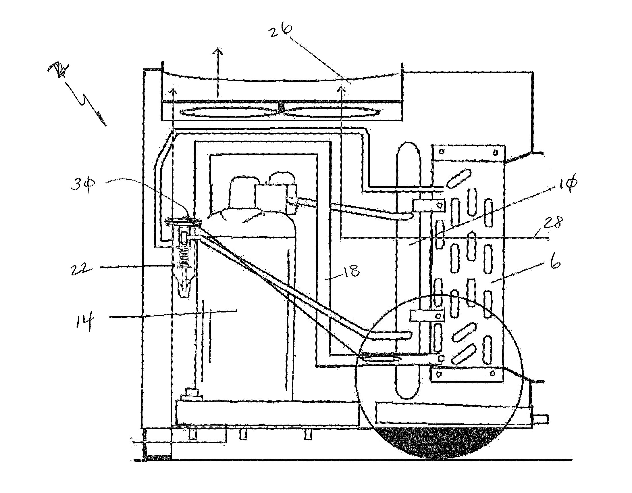
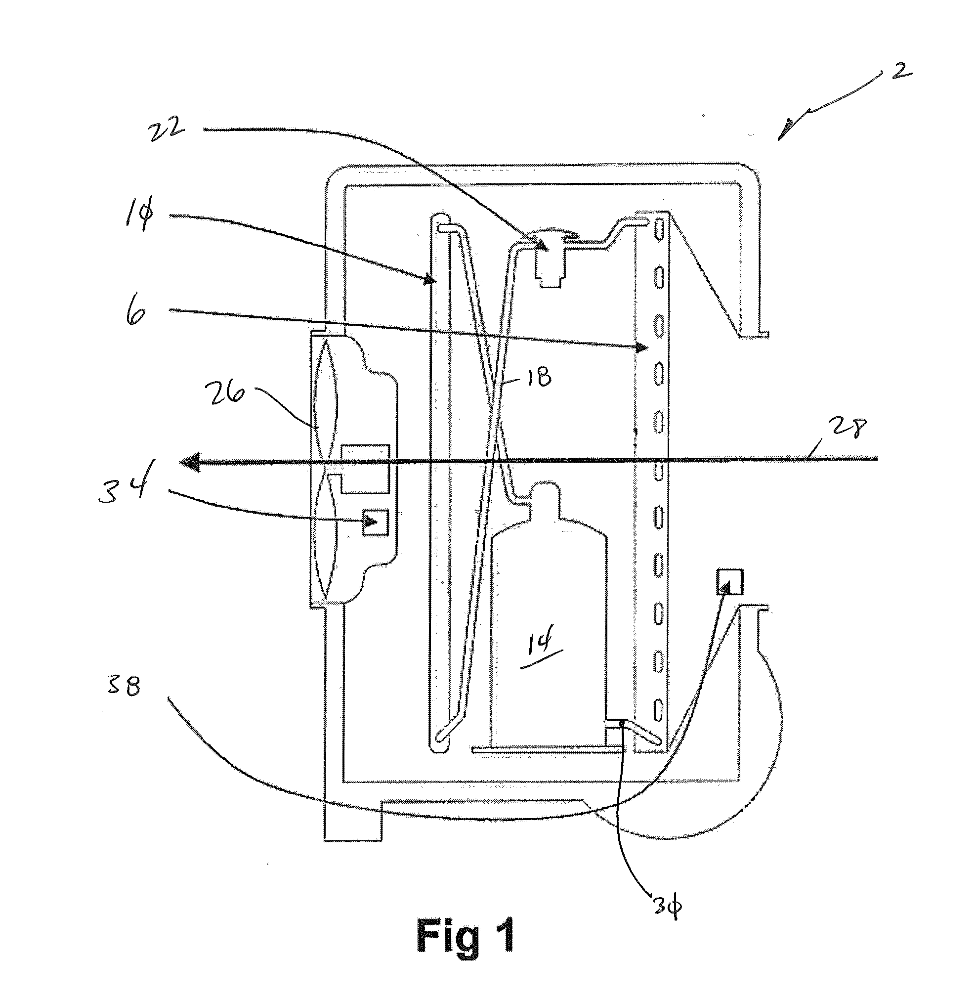
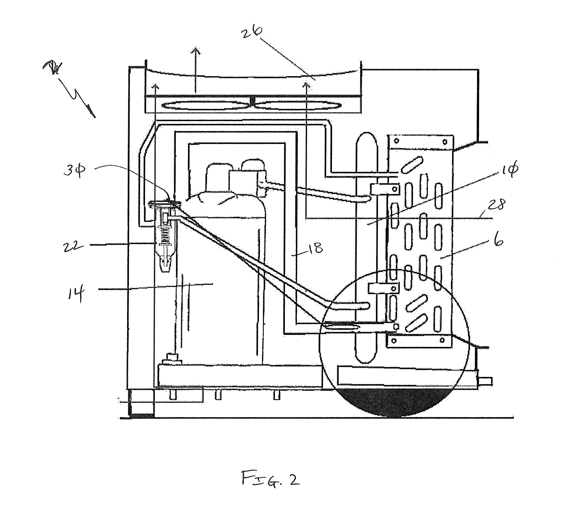
[0049]Referring now to FIGS. 1 and 2, one embodiment of the dehumidifier 2 is shown that includes a fin / tube evaporator 6, a micro channel condenser 10, a compressor 14 and related tubing 18 connecting those components. In addition, a thermal expansion valve (TEV) 22 is associated with the tubing 18 that connects the evaporator 6 to the condenser 10.

[0050]In operation, a fan 26 draws air 28 into the dehumidifier 2 wherein warm, humid air passes over the fins and tubes of the evaporator 6. Refrigerant within the evaporator 6 then is heated, exits the evaporator 6, and is directed to the TEV 22. The refrigerant directed to the TEV 22 is of a greater temperature as result of its heat transfer from the intake air. The temperature of the refrigerant exiting the evaporator 6 is related to varying ambient conditions and is monitored by a sensor 30. Warm vaporized refrigerant is directed to the compressor 14 that compresses the refrigerant and directs it to the condenser 10. Air exiting the...


PUM


Abstract

A transportable dehumidifier system is provided that employs a thermal expansion valve to control the flow of refrigerant therethrough.

Description

CROSS-REFERENCE TO RELATED APPLICATIONS[0001]The following application claims the benefit of U.S. Provisional Patent Application Ser. No. 61 / 219,888, filed Jun. 24, 2009, the entire disclosure of which is incorporated by reference herein.[0002]The following patent application is also related to U.S. Pat. No. 7,281,389, entitled “Enhanced Performance Dehumidifier,” U.S. Patent Application Publication No. 2008 / 0028776, entitled “Enhanced Performance Dehumidifier,” U.S. Pat. No. 7,194,870, entitled “High Performance Dehumidifier,” U.S. Pat. No. 6,370,902, entitled “Apparatus for Dehumidifying Air,” and U.S. Pat. No. 7,246,503 entitled “Enhanced Drying Dehumidifier,” the entire disclosures of which are incorporated by reference herein. This application also directs the attention of one skilled in the art to the Micro Channel Heat Exchangers made by Danfoss, which are described at www.danfoss.com.FIELD OF THE INVENTION[0003]Embodiments of the present invention are generally related to de...

Claims


Application Information

Patent Timeline
Patent Type & Authority Applications(United States)
IPC IPC(8): F25B49/02F25B1/00F25B41/04F25B41/00
CPCF24F3/1405F25B2600/2513F24F2221/125
Inventor STAMM, STEPHENSHIPE, DOUGO'KANE, NICHOLAS BRIAN
Owner KARCHER NORTH AMERICA INC
Why Eureka
Try Eureka