Control device of coal pulverizer

a control device and coal pulverizer technology, which is applied in the direction of combustion process, fuel supply regulation, combustion temperature regulation, etc., can solve the problems of disturbance of coal output from coal pulverizer, delay in coal pulverizer coal output, and inability to perform stable control, etc., to achieve stable response control

Active Publication Date: 2010-12-30
MITSUBISHI POWER LTD
View PDF17 Cites 13 Cited by
  • Summary
  • Abstract
  • Description
  • Claims
  • Application Information

AI Technical Summary

Benefits of technology

[0021]As described above, according to the invention, even if coal properties change, the operation of making the deviation between the coal output pattern during current operation...

Problems solved by technology

This becomes a disturbance in the control of the steam temperature or, steam pressure in the boiler.
Additionally, when the coal feed rate was changed for the load fluctuation of a boiler, the delay of coal output from the coal pulverizer became a disturbance in t...

Method used


Image

  • Control device of coal pulverizer
  • Control device of coal pulverizer
  • Control device of coal pulverizer

Examples


first embodiment

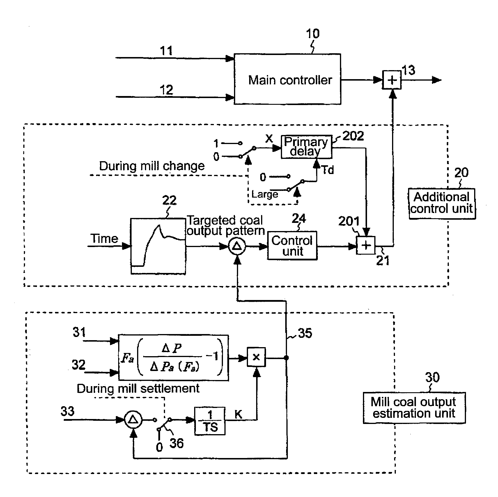
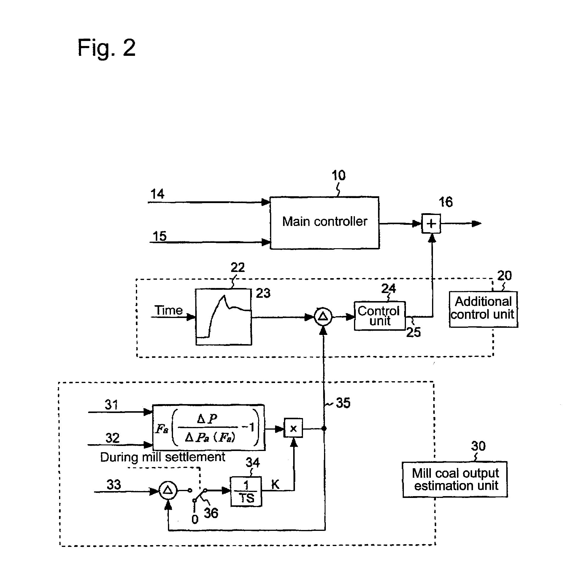
[0037]FIG. 1 is a block diagram illustrating the configuration of a control device according to a first embodiment of the invention. This invention is adapted to add an output signal of a control system using the deviation of a standard mill coal output pattern and a mill coal output pattern during current operation to a primitive signal of a conventional control system as a correction signal, thereby performing mill coal output control more stably, and the first embodiment is configured to use a coal feed rate command value as a command signal associated with a coal feed rate.

[0038]In FIG. 1, the control device of the first embodiment includes a main controller 10 that is a conventional control system, an additional control unit 20, and a mill coal output estimation unit 30.

[0039]The mill coal output estimation unit 30 measures a mill furnace differential pressure (ΔP) 31 and an air flow rate (Fa) 32 that are existing detecting elements, and estimates a mill coal output. The mill f...

second embodiment

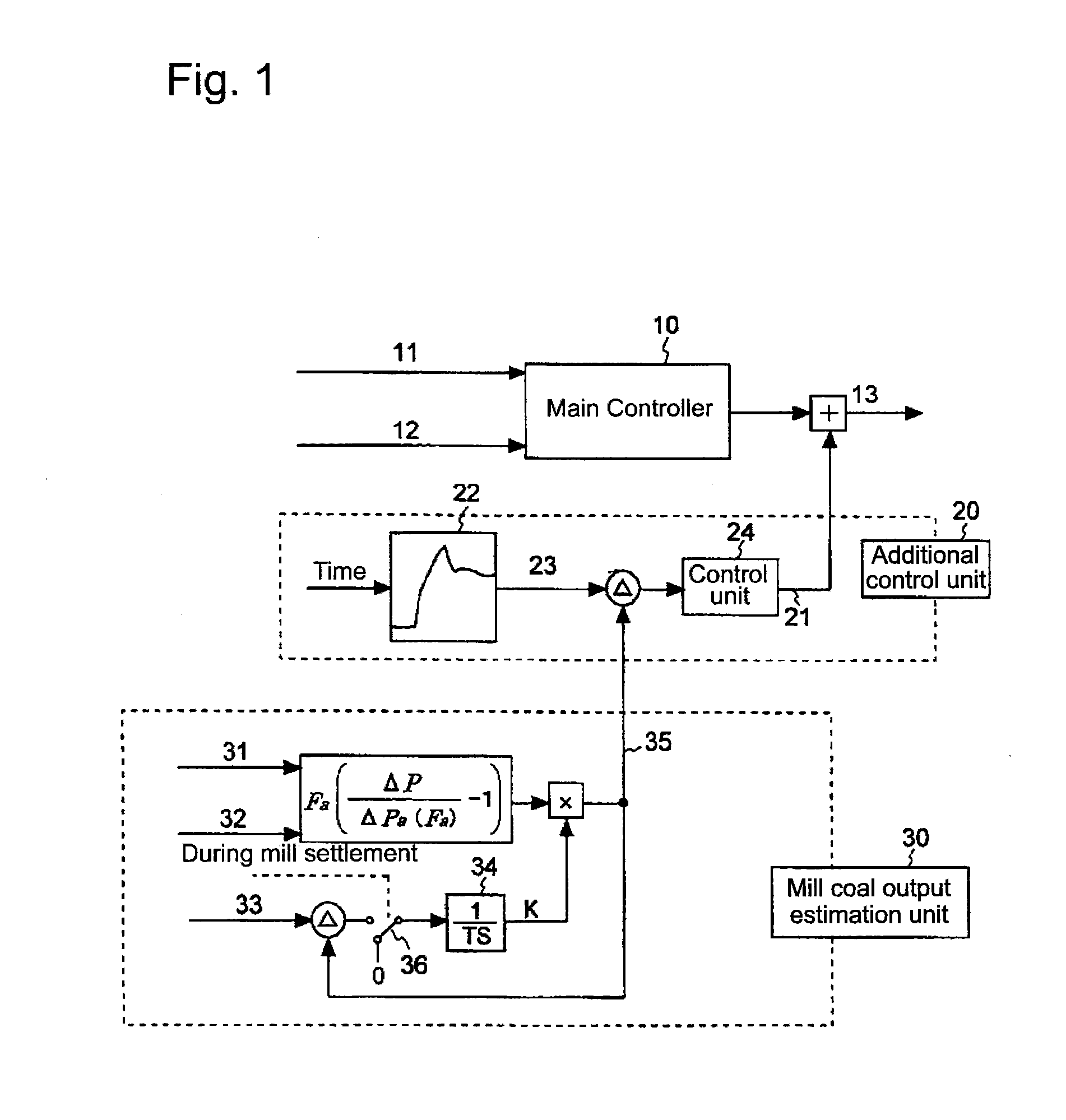
[0050]FIG. 2 is a block diagram illustrating the configuration of a control device according to a second embodiment of the invention.

[0051]The second embodiment is configured to use the MRS rotation frequency of the coal pulverizer as a command signal associated with the coal feed rate.

[0052]In FIG. 2, the control device of the second embodiment includes a main controller 10 that is a conventional control system, an additional control unit 20, and a mill coal output estimation unit 30.

[0053]The mill coal output estimation unit 30 and the additional control unit 20 are the same as those of the first embodiment.

[0054]A mill coal feed rate command 14 and a mill current 15 are input to the main controller 10, and arithmetic processing is performed on the basis of the input, thereby obtaining an MRS rotation frequency command value 16. At this time, an MRS rotation frequency command correction value 25 obtained by the mill coal output estimation unit 30 and the additional control unit 20...

third embodiment

[0056]FIG. 3 is a block diagram illustrating the configuration of a control device according to a third embodiment of the invention.

[0057]The third embodiment is configured to use the load pressure of an oil pressure load device provided in the coal pulverizer as a command signal associated with the coal feed rate. The load pressure represents a pressure applied to the rollers in the coal pulverizer.

[0058]In FIG. 3, the control device of the third embodiment includes a main controller 10 that is a conventional control system, an additional control unit 20, and a mill coal output estimation unit 30.

[0059]The mill coal output estimation unit 30 and the additional control unit 20 are the same as those of the first embodiment.

[0060]A mill coal feed rate command 17 and a roll lift 18 are input to the main controller 10, and arithmetic processing is performed on the basis of the input, thereby obtaining an oil pressure load device pressure setting value 19. At this time, an oil pressure l...


PUM


Abstract

There is provided a control device of a coal pulverizer which enables estimation of a coal output with a precision suited for a purpose. In a control device of a coal pulverizer which pulverizes coal by the coal pulverizer and estimates coal output by which the pulverized coal is output to a boiler, the control device includes a main operation circuit which calculates a command signal associated with a coal feed rate on the basis of detection data from a boiler or a power generator connected to the boiler, and an additional control unit which calculates the deviation between a standard coal output pattern preset in the coal pulverizer, and a current coal output pattern, and adds a calculation result by the additional control unit to the main operation circuit as a correction signal.

Description

TECHNICAL FIELD[0001]The present invention relates to a control device of a coal pulverizer which feeds a pulverized fuel, which is obtained by pulverizing a solid fuel to fine powder, to a boiler along with carrying air.BACKGROUND ART[0002]Generally, in a boiler using various kinds of coal as fuel, because coal properties, such as indexes indicating the hardness of coal, such as a Hardgrove grindability index (HGI) and moisture percentage, are different, the grindability and transportability in a mill are significantly different. When the feed rate of coal from a coal feeder to the mill is changed for the load fluctuation of the boiler, since coal properties are different, the delay of the coal output from the mill is different depending on the each type of coal. This becomes a disturbance in the control of the steam temperature or, steam pressure in the boiler.[0003]As a method of optimizing the operation of such a boiler, for example, Patent Document 1 (Japanese Patent No. 374652...

Claims


Application Information

Patent Timeline
IPC IPC(8): F23N1/00F23K3/00
CPCB02C15/00F23N2039/02F23K2201/10B02C25/00F23N2239/02
Inventor TSUTSUMI, TAKANORIKOMADA, SHIGEHIDETANIGUCHI, MASAHIKOMATSUMOTO, SHINJIFUJIMURA, KOUTAROSUEOKA, YASUHIROMORIYAMA, ISAO
Owner MITSUBISHI POWER LTD
Why Eureka
Try Eureka