Method and apparatus for manufacturing an exhaust pipe assembly

a technology for exhaust pipes and components, applied in the direction of manufacturing tools, soldering devices, roller electrodes, etc., can solve the problems of reducing the power of the engine, reducing the exhaust efficiency, and not being able to obtain sufficient welding strength

Active Publication Date: 2010-12-30
HONDA MOTOR CO LTD
View PDF4 Cites 5 Cited by
  • Summary
  • Abstract
  • Description
  • Claims
  • Application Information

AI Technical Summary

Benefits of technology

[0026]According to the first and second aspects of the present invention, the temperature difference between the outer circumference of the mounting ring and the inner circumference of the pipe can be reduced because the amount of current flow per unit area between the outer circumferential ele

Problems solved by technology

Such resistance against engine exhaust causes decrease in exhaust efficiency, eventually leading to the decrease in power of engine.
Furthermore, coronas are displaced even more toward the mounting ring because the thickness of the mounting ring is large, so that there is a problem that a sufficient

Method used


Image

  • Method and apparatus for manufacturing an exhaust pipe assembly
  • Method and apparatus for manufacturing an exhaust pipe assembly
  • Method and apparatus for manufacturing an exhaust pipe assembly

Examples


Embodiment Construction

[0038]Next is a detailed description of the present invention with reference to the attached drawings.

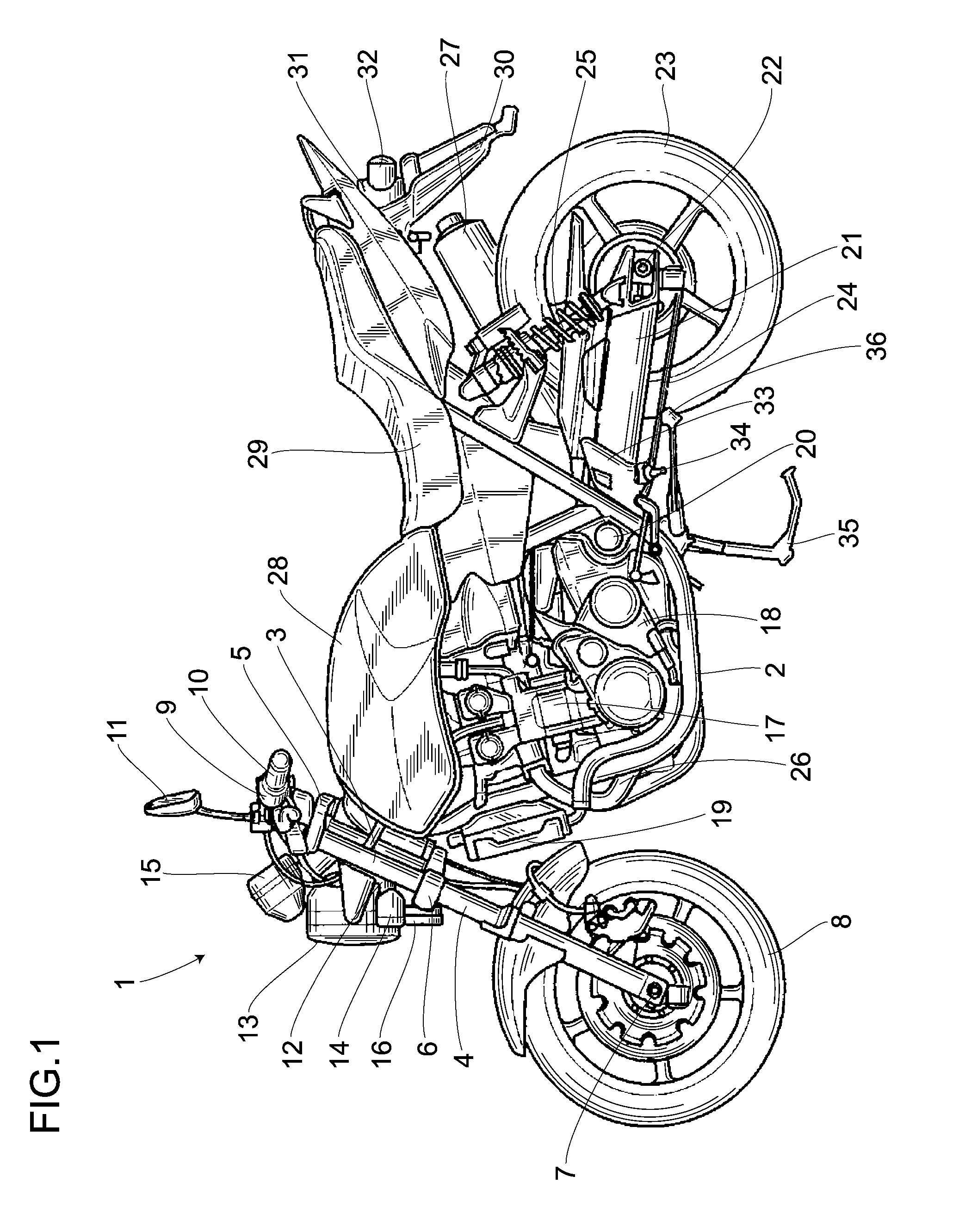
(1) Basic Structure of a Two-wheeled Motor Vehicle

[0039]At first, an explanation will be given of a structure of a two-wheeled motor vehicle including an exhaust pipe assembly according to the present invention. As shown in FIG. 1, the two-wheeled motor vehicle 1 includes a frame body 2 comprising a pair of right and left pipe frames. A steering stem, not shown in FIG. 1, is rotatably supported by a head pipe 3 connected to a front section of the frame body 2. An upper section and a lower section of the steering stem are connected to a top bridge 5 and a bottom bridge 6 of a front fork 4 respectively. The front fork 4 extends downward and supports a front wheel 8 through a front shaft 7 provided near the lower end of the front fork 4.

[0040]A handle pipe 9 is connected to the top bridge 5. A grip 10 and a mirror 11 are attached to the handle pipe 9. A bracket 12 is connected to the f...


PUM

PropertyMeasurementUnit
Temperatureaaaaaaaaaa
Thicknessaaaaaaaaaa
Electric potential / voltageaaaaaaaaaa

Abstract

A method and apparatus for manufacturing an exhaust pipe assembly for an engine which are capable of decreasing a temperature difference between a seam-welded outer surface and a seam-welded inner surface at the time of seam welding. An exhaust pipe assembly manufacturing apparatus 70 comprises an outer circumferential electrode wheel 71 abutted on an outer circumference of a mounting ring 41, a pressing means 102 pressing the outer circumferential electrode wheel 71 to the mounting ring 41, an inner circumferential electrode wheel 103 abutted on an inner circumference of a pipe 40 making up an exhaust pipe assembly 26, a transformer 104 serving as a voltage supply means for supplying a predetermined voltage to the outer and inner circumferential electrode wheels 71 and 103, and a controller 105 for control of voltage of the transformer 104. Thickness T1 of the outer circumferential electrode wheel 71 is formed larger than thickness T2 of the inner circumferential electrode wheel 103.

Description

BACKGROUND OF THE INVENTION[0001]1. Field of the Invention[0002]The present invention relates to a method for manufacturing an exhaust pipe assembly and an apparatus used for the method, and more particularly, to an apparatus for fixing a mounting ring to the exhaust pipe assembly by seam welding.[0003]2. Description of the Related Art[0004]An exhaust pipe assembly used for a vehicle such as a two-wheeled motor vehicle, comprises a plurality of (e.g., four) exhaust pipes, which are each formed by fixing a mounting ring to a first end of a pipe and inserting a mounting flange from a second end of the pipe. Each exhaust pipe is mounted with its first end communicated with an engine, and all the exhaust pipes converge on, for example, a single pipe at their second ends to be connected with a muffler or silencer.[0005]For example, a MIG (Metal Inert Gas) welding or TIG (Tungsten Inert Gas) welding is employed for a method of fixing the mounting ring to the first end of the pipe. However...

Claims


Application Information

Patent Timeline
IPC IPC(8): B23K11/08
CPCB23K11/066B23K2201/006B23K11/3036B23K2101/006
Inventor NAKAJIMA, SHOICHI
Owner HONDA MOTOR CO LTD
Why Eureka
Try Eureka