Laser narrow groove welding apparatus and welding method

Inactive Publication Date: 2010-12-30
HITACHI LTD
View PDF3 Cites 47 Cited by
  • Summary
  • Abstract
  • Description
  • Claims
  • Application Information

AI Technical Summary

Benefits of technology

[0025]Also, according to an aspect of the present invention, a problem that the feeding position of the solid filler metal shifts to the side wall side of the groove

Problems solved by technology

With respect to welding of a thick plate of steel, nickel base alloy and the like, a method of forming a groove in a welding section and filling the groove by buildup welding of a plurality of passes while feeding a filler metal such as a welding wire and welding rod is commonly adopted, however, because the cross-sectional area of the groove increases as the plate thickness increases, the method involves problems such as drop of the manufacturing efficiency due to increase in the number of weldpass and degradation of the welding quality due to increase of deformation and welding distortion.
Accordingly, there was a problem that, even if sound welding of one pass per one layer was possible in the lower part of the groove, lack of fusion was liable to occur between the wa

Method used


Image

  • Laser narrow groove welding apparatus and welding method
  • Laser narrow groove welding apparatus and welding method
  • Laser narrow groove welding apparatus and welding method

Examples


first embodiment

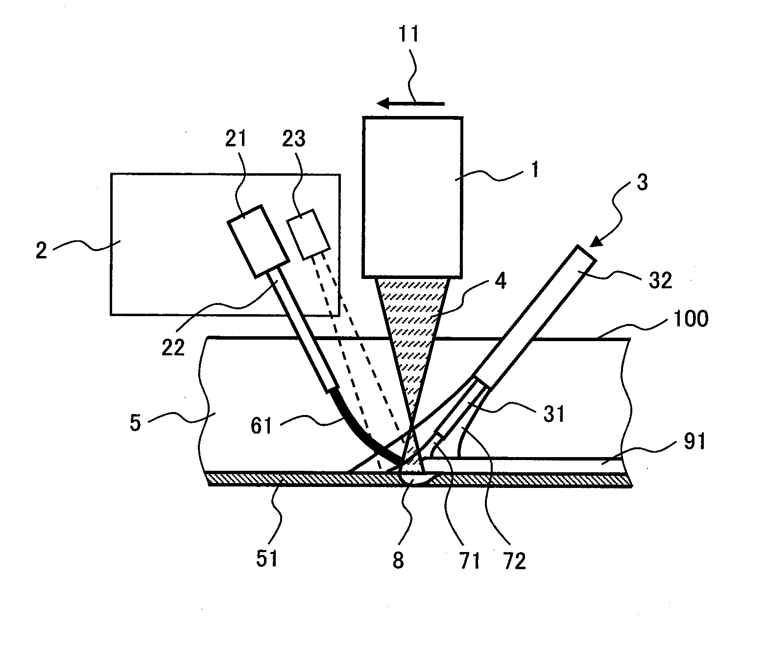
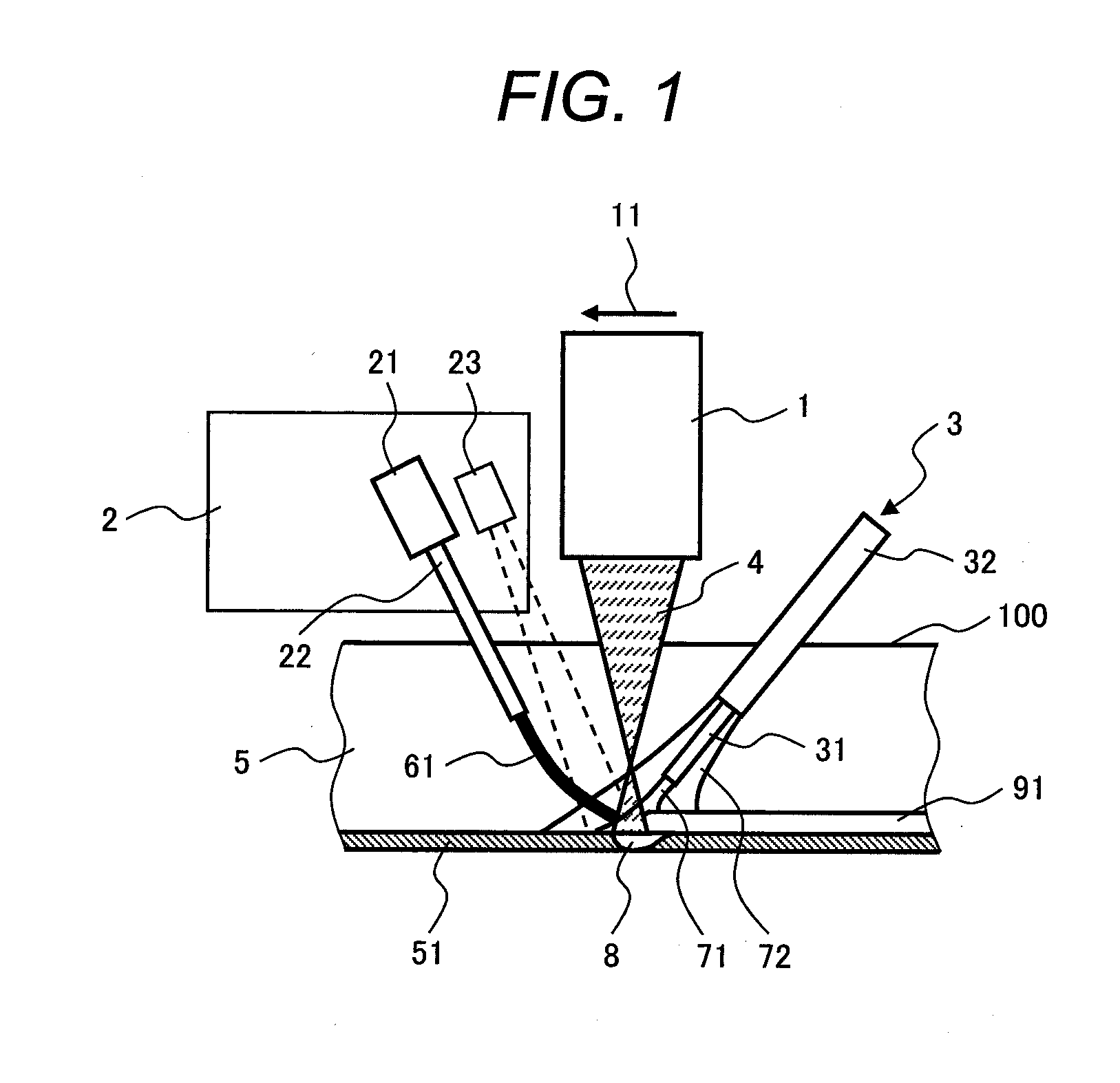
[0034]FIG. 1 is a schematic view showing the constitution of the welding apparatus and the welding process of a first embodiment of the present invention, and roughly shows the inside of the groove as viewed from a side in the welding direction. Reference numeral 1 is a laser beam irradiation head with 10 kw output, 11 is the welding direction, 2 is a filler metal control device, 21 is a filler metal feeder, 22 is a filler metal feeding nozzle, 23 is an imaging camera as a filler metal tip position detecting device, 3 is a shielding gas feeding device, 31 is an inner nozzle, 32 is an outer nozzle, 4 is a laser beam, 5 is a groove, 51 is the bottom of the groove, 61 is a welding wire as a solid filler metal, 71 is a flow of shielding gas from the inner nozzle 31, 72 is a flow of shielding gas from the outer nozzle 32, 8 is a molten pool, 91 is a weld bead, and 100 is a material to be welded. In the first embodiment, the material of the material to be welded was made of stainless stee...

second embodiment

[0041]FIG. 3 is a schematic view showing the constitution of the welding apparatus and the welding process of a second embodiment of the present invention, and roughly shows the inside of the groove as viewed from a side in the welding direction. 1 is a laser beam irradiation head, 11 is a welding direction, 2 is a filler metal control device, 21 is a filler metal feeder, 22 is a filler metal feeding nozzle, 24 is a laser displacement meter, 3 is a shielding gas feeding device, 31 is an inner nozzle, 32 is an outer nozzle, 4 is a laser beam, 5 is a groove, 51 is the bottom of the groove, 62 is a welding rod as a solid filler metal, 71 is a flow of the shielding gas from the outer nozzle 31, 72 is a flow of shielding gas from the inner nozzle 32, 8 is a molten pool, 91 is a weld bead, and 100 is a material to be welded. In the present embodiment, the material of the material to be welded was SM400A (JIS), the material of the welding rod was YGT50 (JIS), and the shielding gas was carb...


PUM

PropertyMeasurementUnit
Sizeaaaaaaaaaa
Feed rateaaaaaaaaaa
Distanceaaaaaaaaaa

Abstract

A welding apparatus and a welding method are employed for laser narrow groove welding which performs welding scanning a laser beam in the welding direction while feeding a solid filler metal into a narrow groove. The welding apparatus includes a laser beam irradiation head having a mechanism periodically oscillating an irradiation point of the laser beam with a predetermined amplitude in the bottom of the groove, and a filler metal control device having a solid filler metal feeder feeding the solid filler metal to the molten pool formed in the bottom of the groove by the laser beam and adjusting the feeding position independent of a motion of the laser beam irradiation head so that the tip position of the solid filler metal detected is constantly positioned in the center of the groove.

Description

CLAIM OF PRIORITY[0001]The present application claims priority from Japanese patent application serial No. 2009-153210 filed on Jun. 29, 2009, the content of which is hereby incorporated by reference into this applicationBACKGROUND OF THE INVENTION[0002]1. Field of the Invention[0003]The present invention relates to a buildup welding apparatus and a welding method for a thick plate by a laser beam.[0004]2. Description of the Related Art[0005]With respect to welding of a thick plate of steel, nickel base alloy and the like, a method of forming a groove in a welding section and filling the groove by buildup welding of a plurality of passes while feeding a filler metal such as a welding wire and welding rod is commonly adopted, however, because the cross-sectional area of the groove increases as the plate thickness increases, the method involves problems such as drop of the manufacturing efficiency due to increase in the number of weldpass and degradation of the welding quality due to ...

Claims


Application Information

Patent Timeline
IPC IPC(8): B23K26/00B23K26/02B23K26/14B23K26/21
CPCB23K26/24
Inventor TSUKAMOTO, TAKESHIKAWANAKA, HIROTSUGUMAEDA, YOSHIHISAIMAOKA, SHINJIKUWANO, TETSUYAHASHIMOTO, TAIJI
Owner HITACHI LTD
Why Eureka
Try Eureka