

Motor
a technology of drive circuit and motor, which is applied in the direction of windings, motor associations, windings, etc., can solve the problems of increasing the size of the motor in the axial and radial directions of the motor, increasing the number of connection points between the windings, and complicated wiring of the winding to the switching element, so as to reduce the size of the motor
- Summary
- Abstract
- Description
- Claims
- Application Information
AI Technical Summary
Benefits of technology
Problems solved by technology
Method used
Image

Examples
first embodiment
[0038]As shown in FIG. 3, a motor 10 according to a first embodiment of the present invention is a brushless motor used in an electric power steering 1. The motor 10 engages with a gear 3 of a column shaft 2 and rotates both in forward and reverse directions based on a vehicle speed signal sent via, for example, a controller area network (CAN) and a steering torque signal detected by a torque sensor 4, thereby producing steering assist force.
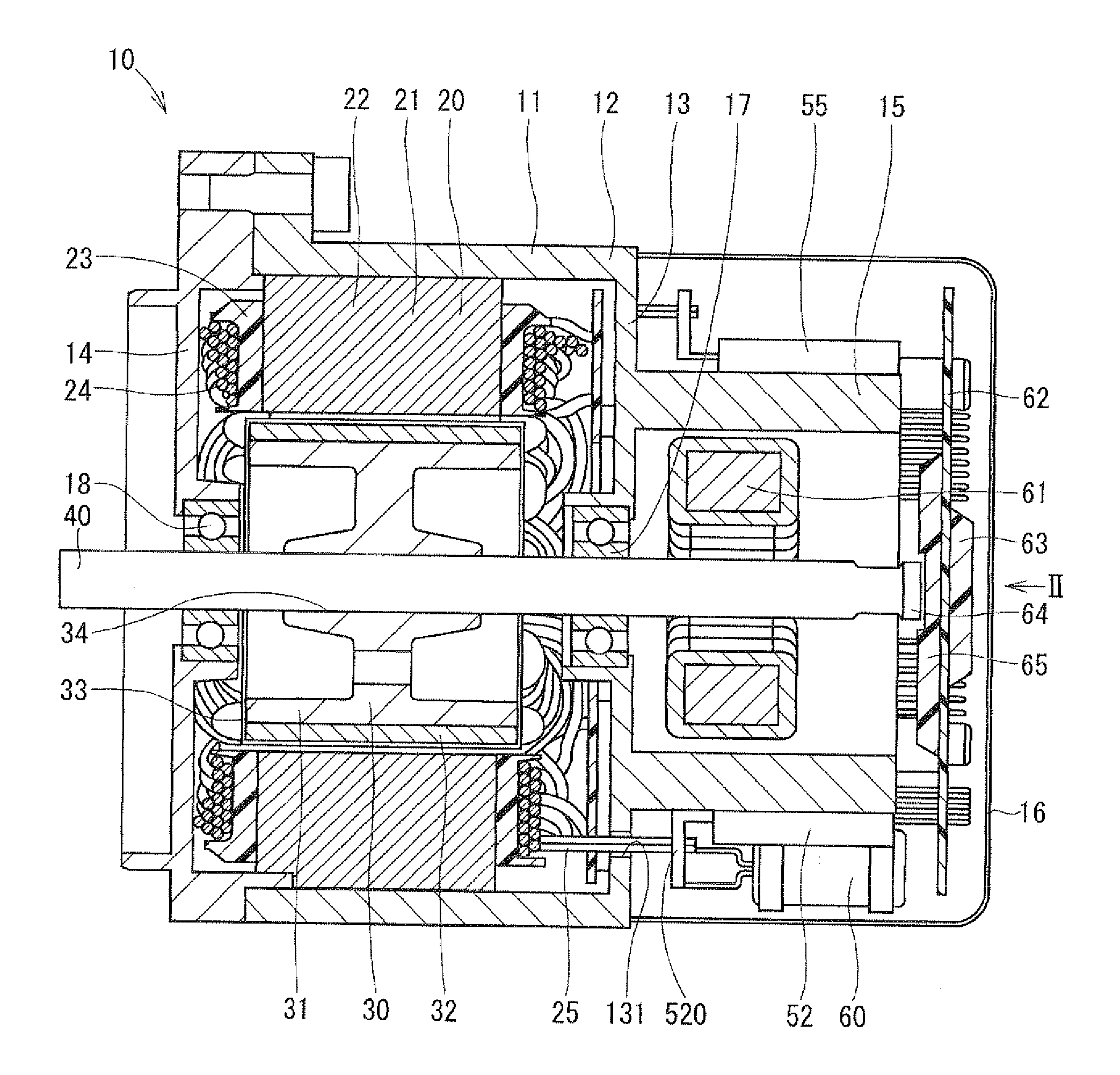
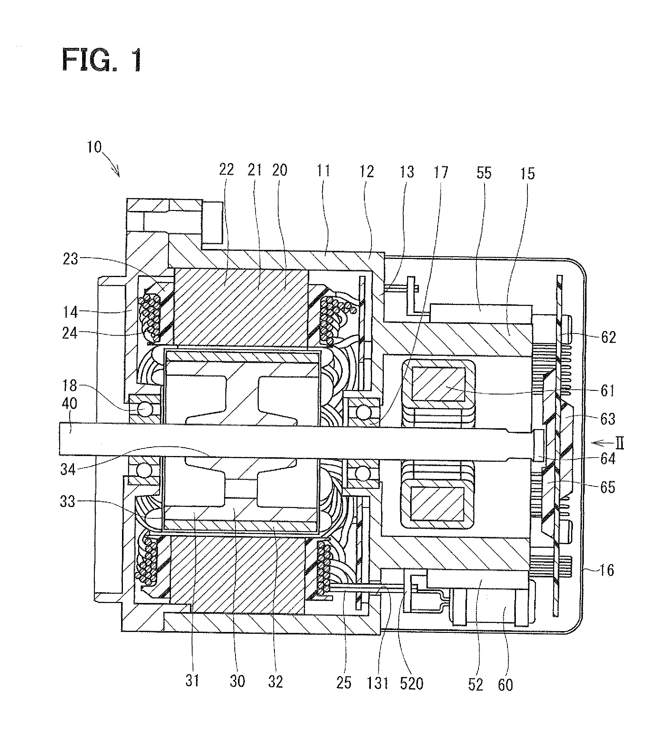
[0039]As shown in FIG. 1, the motor 10 includes a housing 11 as a motor casing, a cover 16, a stator 20, a rotor 30, a shaft 40, and power modules 51-56 serving as drive modules.
[0040]For example, the housing 11 can be made of aluminum and have a substantially tubular shape. According to the first embodiment, the housing 11 includes a tube portion 12 as a surrounding wall, first and second side walls 13, 14, and a heatsink 15. The tube portion 12 has a tubular shape. The first and second side walls 13, 14 are joined to first and second ends of t...
second embodiment
[0083]A second embodiment of the present invention is described below with reference to FIGS. 9, 10. A difference of the second embodiment from the first embodiment is as follows.
[0084]As shown in FIG. 9, according to the second embodiment, the pair of windings W1, W2 of a three-phase winding set 801 is located between the pair of windings U1, U2 and the pair of windings V4, V3 of a three-phase winding set 701. Likewise, the pair of windings U4, U3 of the three-phase winding set 801 are located between the pair of windings V4, V3 and the pair of windings W3, W4 of the three-phase winding set 701. Likewise, the pair of windings V2, V1 of the three-phase winding set 801 are located between the pair of windings W3, W4 and the pair of windings U2, U1 of the three-phase winding set 701. Therefore, as indicated by a solid line 92 in FIG. 10, the pair of windings U2, U1, the pair of windings V4, V3, and the pair of windings W3, W4 of the three-phase winding set 701 are spaced about 120 deg...
third embodiment
[0098]A third embodiment of the present invention is described below with reference to FIGS. 11-13. A difference of the third embodiment from the preceding embodiments is as follows.
[0099]As shown in FIG. 11, according to the third embodiment, the windings of the stator 20 are connected in a Y configuration to form a three-phase winding set 702. The three-phase winding set 702 is connected to the first inverter circuit 59.
[0100]Further, as shown in FIGS. 12, 13, the windings of the stator 20 are connected in a Y configuration to form a three-phase winding set 802. The three-phase winding set 802 is connected to the second inverter circuit independent of the first inverter circuit 59.
[0101]The pair of the windings V4, V3, the pair of the windings U2, U1, and the pair of the windings W3, W4 of the three-phase winding set 702 are arranged adjacent in the rotation direction of the rotor 30. Likewise, the pair of the windings V2, V1, the pair of the windings U4, U3, and the pair of the w...
PUM
 Abstract
Description
Claims
Application Information