Sensorless control of salient-pole machines

a technology of salient-pole machines and sensors, which is applied in the field of machinery control and driving, can solve the problems of reducing the reliability of the controlled machine, the signal-to-noise ratio of this voltage is too poor at low speeds to estimate the motion state, and the rotor position cannot be estimated from the induced voltage, so as to reduce costs, improve reliability, and improve reliability

Inactive Publication Date: 2010-12-30
UNIV GENT
View PDF10 Cites 13 Cited by
  • Summary
  • Abstract
  • Description
  • Claims
  • Application Information

AI Technical Summary

Benefits of technology

[0009]It is an object of the present invention to provide good systems and methods for controlling a salient-pole machine. It is an advantage of embodiments according to the present invention that these may avoid the use of a mechanical transducer, hence increasing reliability and reducing costs. It is an advantage of embodiments according to embodiments of the present invention to provide a controller which does not require an estimation of the induced voltage, a machine model or additional test pulses which would prolong the test sequence. It is an advantage of embodiments according to the present invention that systems and methods are provided with which steady-state current distortion with consequent torque disturbance and audible noise can be reduced, e.g. strongly reduced or even avoided.

Problems solved by technology

Due to important temperature variations within the machine, as well as mechanical vibrations, these sensors can fail, consequently reducing the reliability of the controlled machine.
However, the signal-to-noise ratio of this voltage is too poor at low speeds to estimate the motion states.
Moreover, at standstill, the rotor position can't be estimated from the induced voltage.
These filters can generate an important phase delay in the control loop, reducing the dynamic behavior of the drive.
Nevertheless, in this method the estimated rotor position isn't obtained in one sampling period but converges in several periods to the real one through iteration.

Method used


Image

  • Sensorless control of salient-pole machines
  • Sensorless control of salient-pole machines
  • Sensorless control of salient-pole machines

Examples


Embodiment Construction

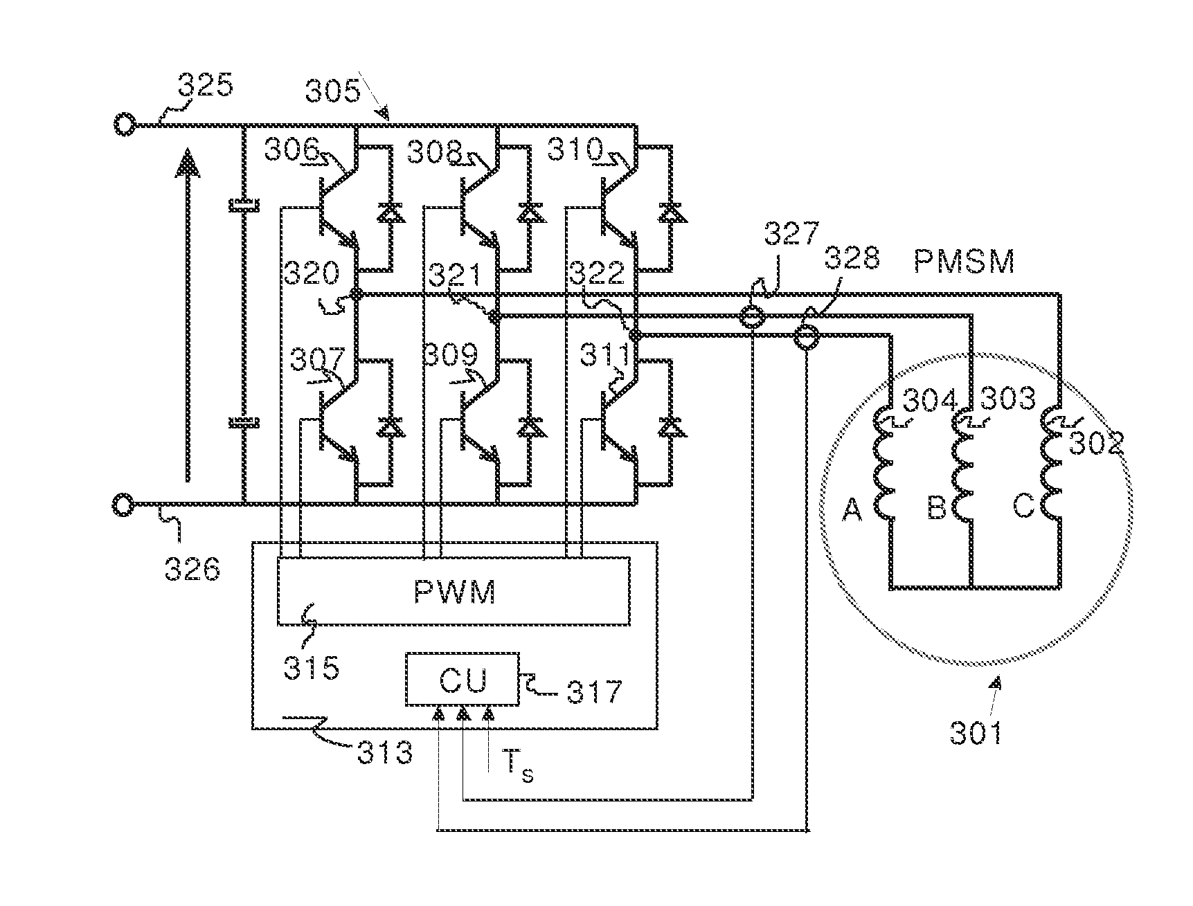
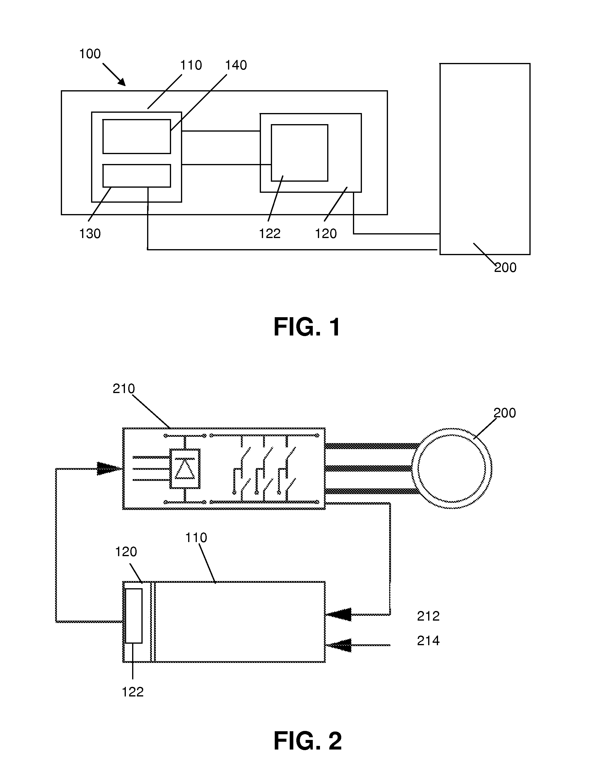
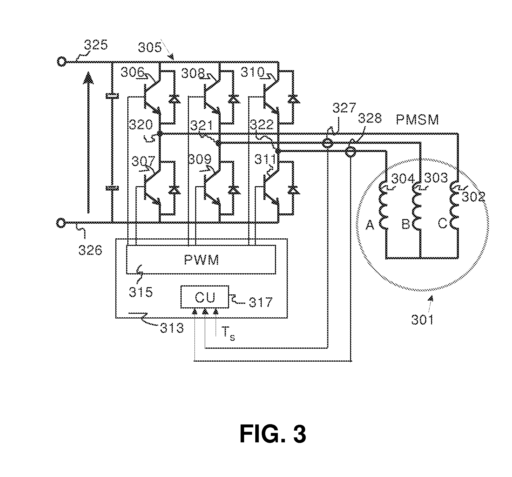
[0063]The present invention will be described with respect to particular embodiments and with reference to certain drawings but the invention is not limited thereto but only by the claims. The drawings described are only schematic and are non-limiting. In the drawings, the size of some of the elements may be exaggerated and not drawn on scale for illustrative purposes. The dimensions and the relative dimensions do not correspond to actual reductions to practice of the invention. Furthermore, the terms first, second, third and the like in the description and in the claims, are used for distinguishing between similar elements and not necessarily for describing a sequence, either temporally, spatially, in ranking or in any other manner. It is to be understood that the terms so used are interchangeable under appropriate circumstances and that the embodiments of the invention described herein are capable of operation in other sequences than described or illustrated herein. It is to be no...


PUM


Abstract

A controller (100) for controlling a salient-pole machine (200) is disclosed. The controller (100) is adapted to determine at least one operational parameter of the salient-pole machine (200), such as for example a rotor position, a rotor angle or a steady-state voltage. The controller (100) comprises a calculating unit for calculating test pulse properties for test pulses for supply to phase inputs of the salient-pole machine. The test pulse properties thereby comprise a pulse width and the calculating unit (110) is adapted for determining the pulse width in an adaptive manner.

Description

TECHNICAL FIELD OF THE INVENTION [0001]The present invention relates to the field of machinery such as for example motors. More particularly, the present invention relates to the field of control and driving of machinery, such as for example salient-pole machines. The method and systems are applicable in a large number of fields, e.g. in advanced energy generation.BACKGROUND OF THE INVENTION[0002]In order to control the motion states of a synchronous machine in a stable manner it is required to measure the rotor position. This can be achieved by mounting mechanical devices such as encoders or resolvers on the shaft of the machine or by placing hall-sensors or search coils within the machine. Due to important temperature variations within the machine, as well as mechanical vibrations, these sensors can fail, consequently reducing the reliability of the controlled machine. For this reason, as well as to reduce cost and extra cabling, the motion states are estimated instead of measured...

Claims


Application Information

Patent Timeline
Patent Type & Authority Applications(United States)
IPC IPC(8): H02P6/18
CPCH02P6/16H02P6/165H02P25/021H02P21/146H02P21/04H02P6/17H02P21/18H02P25/024
Inventor DE BELIE, FREDERIKMELKEBEEK, JAN
Owner UNIV GENT
Why Eureka
Try Eureka