
Device and method for converting spatial audio signal

a technology of spatial audio signal and audio signal, applied in signal processing, stereophonic arrangments, electrical apparatus, etc., can solve the problems of loss of out-of-head sensation, loss of binaural playback experience, and inability to accurately localize sound sources, so as to improve the reproduction of transient sounds

Active Publication Date: 2010-12-30
HARPEX LTD
View PDF4 Cites 105 Cited by
  • Summary
  • Abstract
  • Description
  • Claims
  • Application Information

AI Technical Summary

Benefits of technology

[0016]Such audio processor provides an advantageous conversion of the multi-channel input signal due to the combination of parametric plane wave decomposition extraction of directions for dominant sound sources for each frequency band and the selection of at least one virtual loudspeaker position coinciding with a direction for at least one dominant sound source.
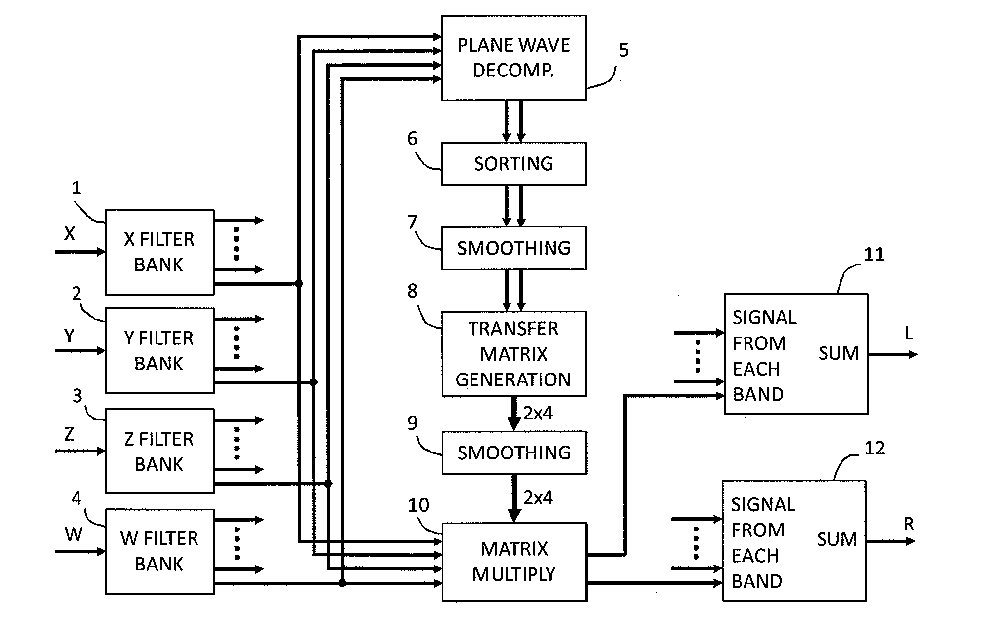
[0034]By way of example, one can mention amplitude panning, vector base amplitude panning, wave field synthesis, virtual microphone characteristics and ambisonics equivalent panning. These methods all produce output signals suitable for playback over an array of loudspeakers. One might also choose to use spherical harmonics as transfer functions, in which case the output signals are suitable for decoding by a higher-order ambisonic decoder. Other transfer functions may also be suitable. Especially, such audio processor may be implemented by a decoding matrix corresponding to the determined virtual loudspeaker positions and a transfer function matrix corresponding to the directions and the selected panning method, combined into an output transfer matrix prior to being applied to the audio input signals. Hereby a smoothing may be performed on transfer functions of such output transfer matrix prior to being applied to the input signals, which will serve to improve reproduction of transient sounds.
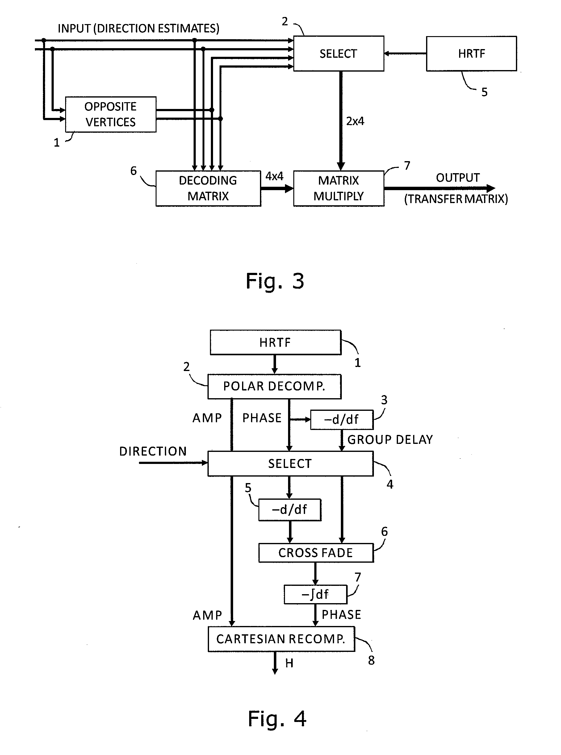
[0035]In order to generate a binaural two-channel output signal, the audio processor may comprise a binaural synthesizer unit arranged to generate first and second audio output signals by applying Head-Related Transfer Functions to each of the virtual loudspeaker signals. Especially, such audio processor may be implemented by a decoding matrix corresponding to the determined virtual loudspeaker positions and a transfer function matrix corresponding to the Head-Related Transfer Functions being combined into an output transfer matrix prior to being applied to the audio input signals. Hereby a smoothing may be performed on transfer functions of such output transfer matrix prior to being applied to the input signals, which will serve to improve reproduction of transient sounds.

Problems solved by technology

In the case of conversion of B-format signals to multiple loudspeakers in a loudspeaker array, there is a well recognized problem due to the spreading of individual virtual sound sources over a large number of playback speaker elements.
In the case of binaural playback of B-format signals, the approximations inherent in the B-format sound field can lead to less precise localization of sound sources, and a loss of the out-of-head sensation that is an important part of the binaural playback experience.
However, that invention does not address issues related to the precision of localization or other aspects of sound reproduction quality.
The problem with these methods is that the direction estimate is generally incorrect in the case where more than a single sound source emits sound at the same time and within the same frequency band.
This leads to imprecise or incorrect localization when there is more than one sound source is present and when echoes interfere with the direct sound from a single source.

Method used


Image

  • Device and method for converting spatial audio signal
  • Device and method for converting spatial audio signal
  • Device and method for converting spatial audio signal

Examples


Embodiment Construction

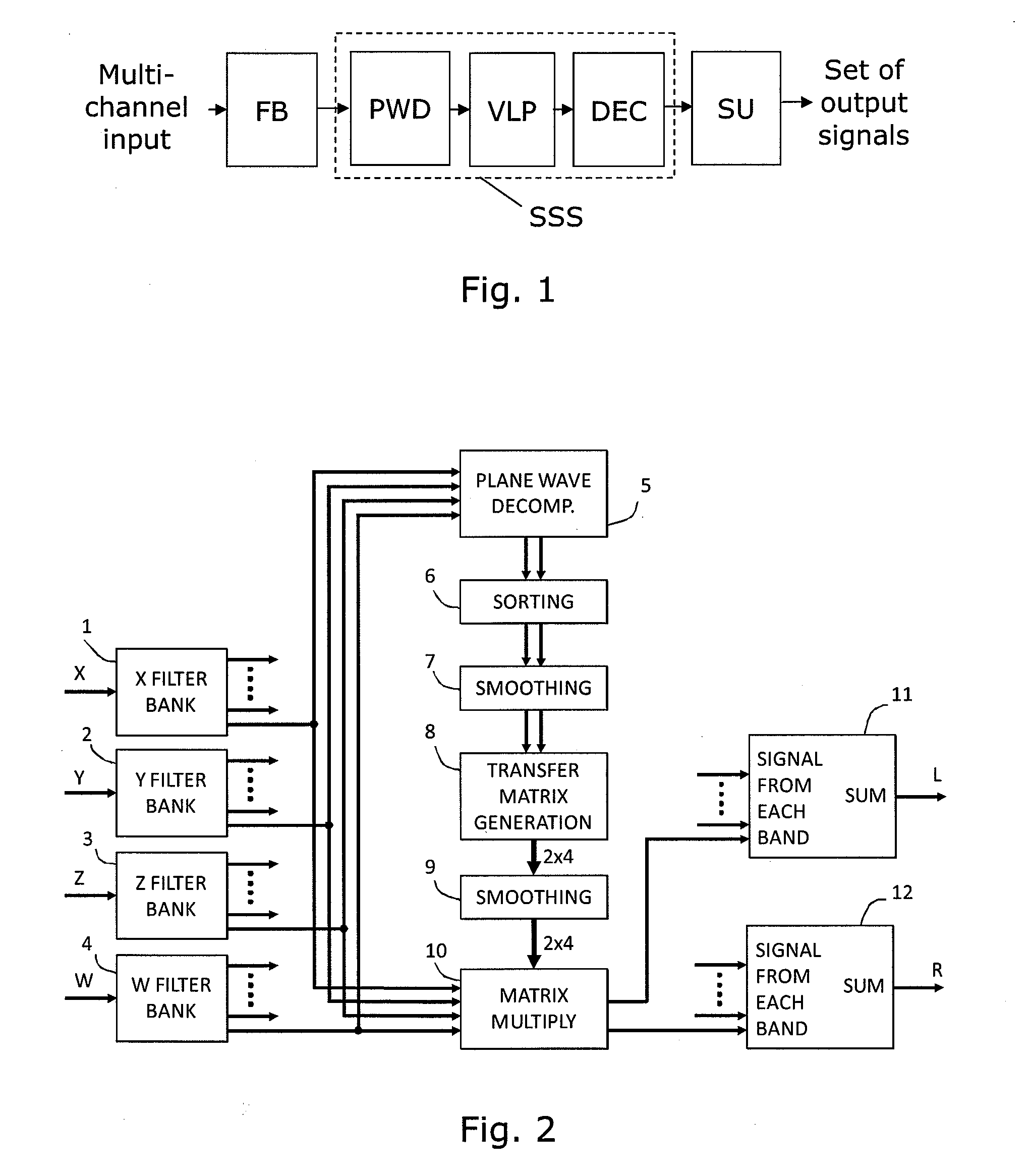
[0053]FIG. 1 shows an audio processor component with basic components according to the invention. Input to the audio processor is a multi-channel audio signal. This signal is split into a plurality of frequency bands in a filter bank, e.g. in the form of an FFT analysis performed on each of the plurality of channels. A sound source separation unit SSS is then performed on the frequency separated signal. First, a parametric plane wave decomposition calculation PWD is performed on each frequency band in order to determine one or two dominant sound source directions. The dominant sound source directions are then applied to a virtual loudspeaker position calculation algorithm VLP serving to select a set of virtual sound source or virtual loudspeaker directions, e.g. by rotation of a fixed set of virtual loudspeaker directions, such that the one or both, in case of two, dominant sound source directions coincide with respective virtual loudspeaker directions. The precise operation perform...


PUM


Abstract

An audio processor for converting a multi-channel audio input signal, such as a B-format sound field signal, into a set of audio output signals, such as a set of two or more audio output signals arranged for headphone reproduction or for playback over an array of loudspeakers. A filter bank splits each of the input channels into frequency bands. The input signal is decomposed into plane waves to determine one or two dominant sound source directions. The(se) are used to determine a set of virtual loudspeaker positions selected such that the dominant direction(s) coincide(s) with virtual loudspeaker positions. The input signal is decoded into virtual loudspeaker signals corresponding to each of the virtual loudspeaker positions, and the virtual loudspeaker signals are processed with transfer functions suitable to create the illusion of sound emanating from the directions of the virtual loudspeakers. A high spatial fidelity is obtained due to the coincidence of virtual loudspeaker positions and the determined dominant sound source direction(s). Improved performance can be obtained in the case where Head-Related Transfer Functions are used by differentiating the phase of a high frequency part of the HRTFs with respect to frequency, followed by a corresponding integration of this part with respect to frequency after combining the components of HRTFs from different directions.

Description

CROSS-REFERENCE TO RELATED APPLICATIONS[0001]This application claims the benefit of priority to European Patent Application No. 09163760.3, filed Jun. 25, 2009, and Norwegian Application No. 20100031, filed Jan. 8, 2010, both of which are hereby expressly incorporated by reference in their entireties.FIELD OF THE INVENTION[0002]The invention relates to the field of audio signal processing. More specifically, the invention provides a processor and a method for converting a multi-channel audio signal, such as a B-format sound field signal, into another type of multi-channel audio signal suited for playback via headphones or loudspeakers, while preserving spatial information in the original signal.BACKGROUND OF THE INVENTION[0003]The use of B-format measurements, recordings and playback in the provision of more ideal acoustic reproductions which capture part of the spatial characteristics of an audio reproduction are well known.[0004]In the case of conversion of B-format signals to mul...

Claims


Application Information

Patent Timeline
Patent Type & Authority Applications(United States)
IPC IPC(8): H04R5/00
CPCH04R3/12H04R2430/03H04S3/004H04S2420/13H04S2400/11H04S2420/01H04S2420/07H04S2400/01
Inventor BERGE, SVEIN
Owner HARPEX LTD
Learn More