Ambient noise compensation system

a noise compensation and ambient noise technology, applied in the direction of transducer protection circuits, amplification control, electric devices, etc., can solve the problems of increasing the difficulty of tasks, contributing to the ambient noise of the listening area, and the outdoor listening area often encountering increasing and decreasing ambient noise, etc., to achieve the desired volume of sound

Inactive Publication Date: 2010-12-30
MFG RESOURCES INT INC
View PDF8 Cites 25 Cited by
  • Summary
  • Abstract
  • Description
  • Claims
  • Application Information

AI Technical Summary

Benefits of technology

[0009]To eliminate the problems associated with other noise compensation systems, the claimed invention determines a reference value. To determine the reference value a digital audio signal may be run through a low pass filter and down sampled. The resultant signal consisting of the frequency components in the audible range is then subjected to a numerical process having a time window. The numerical process produces the reference value. Next, the ambient noise compensation system needs to determine the actual measured sound levels in the listening area. To accomplish this, a sound pick-up is placed in the listening area. The information received by the sound pick-up is digitalized and subjected to a numerical process having a time window producing a measured value. The measure value is the combination of the desired sound and ambient noise present in the listening area allowing the system to distinguish between the desired sound and the ambient noise by comparing the reference and measured values.
[0010]To accurately compensate for the ambient noise the system employs a predictive value. The predictive value is obtained by applying a transformation function to the reference value. To ensure the most accurate predictive value, the transformation function should be analyzed in a low noise or noiseless environment. After the predictive value is obtained it is then compared to the measured value to derive the difference. It is this difference that used to determine whether the volume of the desired sound needs to be increased or decreased to maintain the desired sound at an audible and comfortable level. If a change in volume is required the ambient noise compensation system may adjust the gain of the sound system output automatically.

Problems solved by technology

However, this task becomes increasingly difficult when the ambient noise increases and decreases over time.
Outdoor listening areas frequently encounter increasing and decreasing ambient noise.
In addition, outdoor listening areas have the possibility of rain and wind contributing to the ambient noise of the listening area.
A problem that has plagued ambient noise compensation systems has been the system's ability to determine the sound contribution from the desired sound and the ambient noise to the sound level in the listening area.
It is precisely this differentiation that some existing sound systems fail to account for when analyzing the sound level of the listening area received by the microphone and in turn begin a cycle where the volume of the desired sound is continuously increased making the volume uncomfortable in the listening area.
Although analyzing the sound level from the listening area, these techniques still have problems.
Some techniques have potential error rates greater than the difference between the desired sound and the ambient noise.
Other utilized techniques have problems with delay in the calculations or are complex in their design.
Still other techniques are limited to certain applications where the ambient noise must be monitored in ways other than through the use of microphones.
In addition, current ambient noise compensation systems fail to account for multiple listening areas.
These failures are only compounded in attempting to adjust desired sound levels in multiple listening areas where the listening areas may overlap one another.
This cycle may lead to an uncomfortable volume increase across all listening areas.

Method used


Image

  • Ambient noise compensation system
  • Ambient noise compensation system
  • Ambient noise compensation system

Examples


Embodiment Construction

)

[0017]Exemplary embodiments are directed to an ambient noise compensation system and a method of ambient noise compensation. Exemplary embodiments may be used for outdoor and indoor listening areas and outdoor and indoor venues having multiple listening areas.

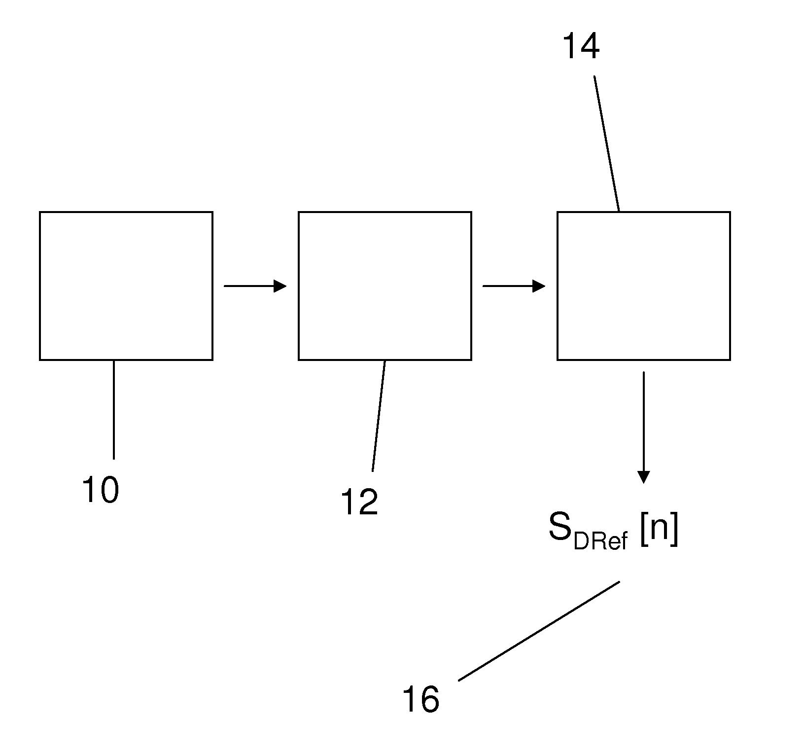
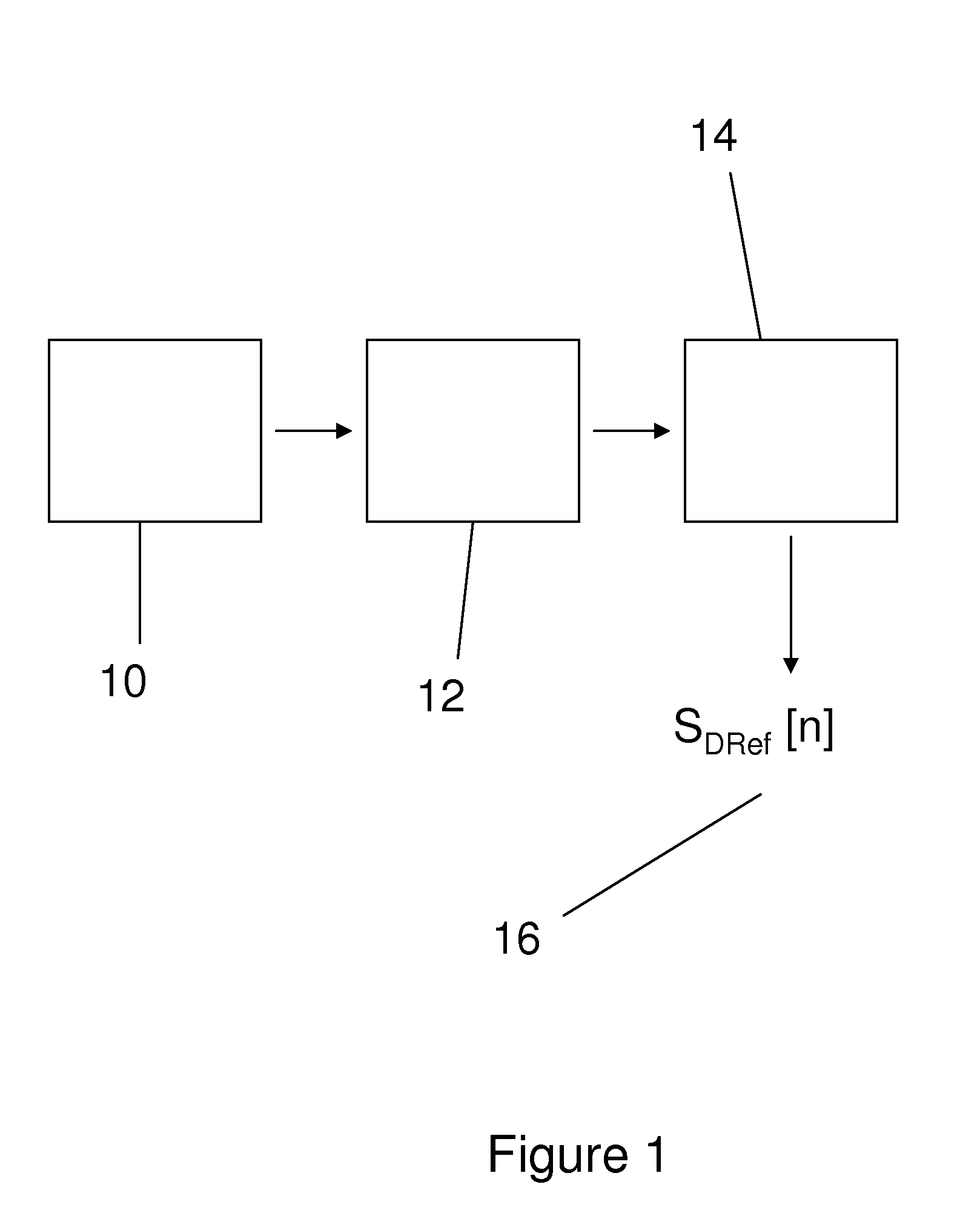
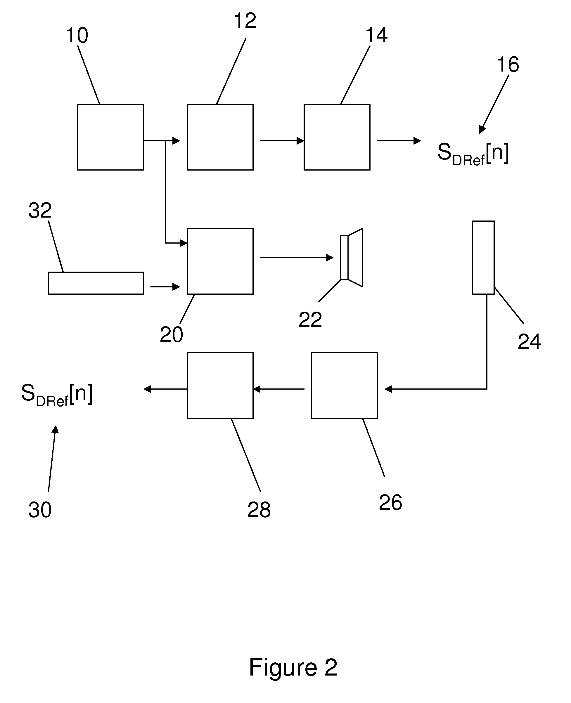
[0018]A sound system that may be used with exemplary embodiments may be a digital audio system. It should be recognized by one skilled in the art that an analog system may also be used. To obtain a reference value 16 a digital audio system may be played at a high resolution and may have highly sampled data in the digital side of the system. This high-frequency sampled audio data 10 may be down sampled and pass through a low pass filter 12. The down sampling and passage through a low pass filter may ensure that only frequency components in the audible frequency are transmitted. The signal is then subjected to a numerical process with a time window 14. The resultant value is the reference value (SDRef[n]) 16 and may stand for th...


PUM


Abstract

An ambient noise compensation system having an automatic gain control to adjust the volume of a desired sound in a listening area. A sound pick-up may be placed in the listening area to capture the sound level, including both the desired sound and ambient noise. A measured value is then determined based on the sound level received by the sound pick-up. The measured value may then be compared to a predictive value to determine an acceptable range. The gain control automatically adjusts the volume of the desired sound to maintain the measured sound within the acceptable range.

Description

CROSS-REFERENCE TO RELATED APPLICATIONS[0001]This application claims priority to U.S. Application No. 61 / 122,774, filed Dec. 16, 2008, which is incorporated hereby by reference as if fully rewritten herein.TECHNICAL FIELD[0002]The present invention relates generally to sound processing systems. More particularly, the invention related to sound processing systems that automatically adjust the sound output based on the ambient noise level in an outdoor listening area.BACKGROUND AND SUMMARY OF THE INVENTION[0003]In any listening area, compensation must be made to deal with ambient noise. Sound systems must be able to play the desired sound at a level sufficient to overcome the ambient noise. The desired sound produced from the sound system must be able to be heard over the ambient noise in the listening area. To accomplish this, measurements of the ambient noise in the listening area are taken and the volume of the desired sound adjusted accordingly. However, this task becomes increasi...

Claims


Application Information

Patent Timeline
Patent Type & Authority Applications(United States)
IPC IPC(8): H03G3/20
CPCH04R3/007H03G3/32
Inventor DUNN, WILLIAMBAEK, HANWOOK
Owner MFG RESOURCES INT INC
Why Eureka
Try Eureka