Absolute acceleration sensor for use within moving vehicles

Inactive Publication Date: 2010-12-30
VISION WORKS IP CORP
View PDF86 Cites 84 Cited by
  • Summary
  • Abstract
  • Description
  • Claims
  • Application Information

AI Technical Summary

Benefits of technology

[0013]The present invention provides systems and methods for warning drivers of other vehicles of any possibility that a subject vehicle will brake and/or that the following vehicle may need to decelerate. This warning occurs earlier than warnings provide

Problems solved by technology

Though all street legal motor vehicles have brake lamps configured to signal other drivers of braking, these signals do not warn following drivers of imminent braking.
However, the system fails to precisely account for gravitational forces, limiting its effectiveness to deceleration regimes where gravity's effect is minimal and reducing its effectiveness as an early warning system.
This sensitivity complicates any system that attempts to detect low levels of acceleration by using accelerometers within moving vehicles, since the system must account for the wide variety of orientations of the accelerometer relative to the earth's gravity introduced as the vehicle travels uphill, downhill, through cambered or off-camber curves, and on cambered grades.
However, the reliance of this device on a threshold deceleration reduces its effectiveness as an early warning system.
Even a short delay between the time when the subject vehicle begins to slow down and the time when a following vehicle begins to slow can result in a rapid closure of the gap, or following distance, between the vehicles, and a potential collision.
Consequently, the shorter the following distance between vehicles, the smaller the margin of error will be for

Method used


Image

  • Absolute acceleration sensor for use within moving vehicles
  • Absolute acceleration sensor for use within moving vehicles
  • Absolute acceleration sensor for use within moving vehicles

Examples


example 1

Rear End Collision Avoidance

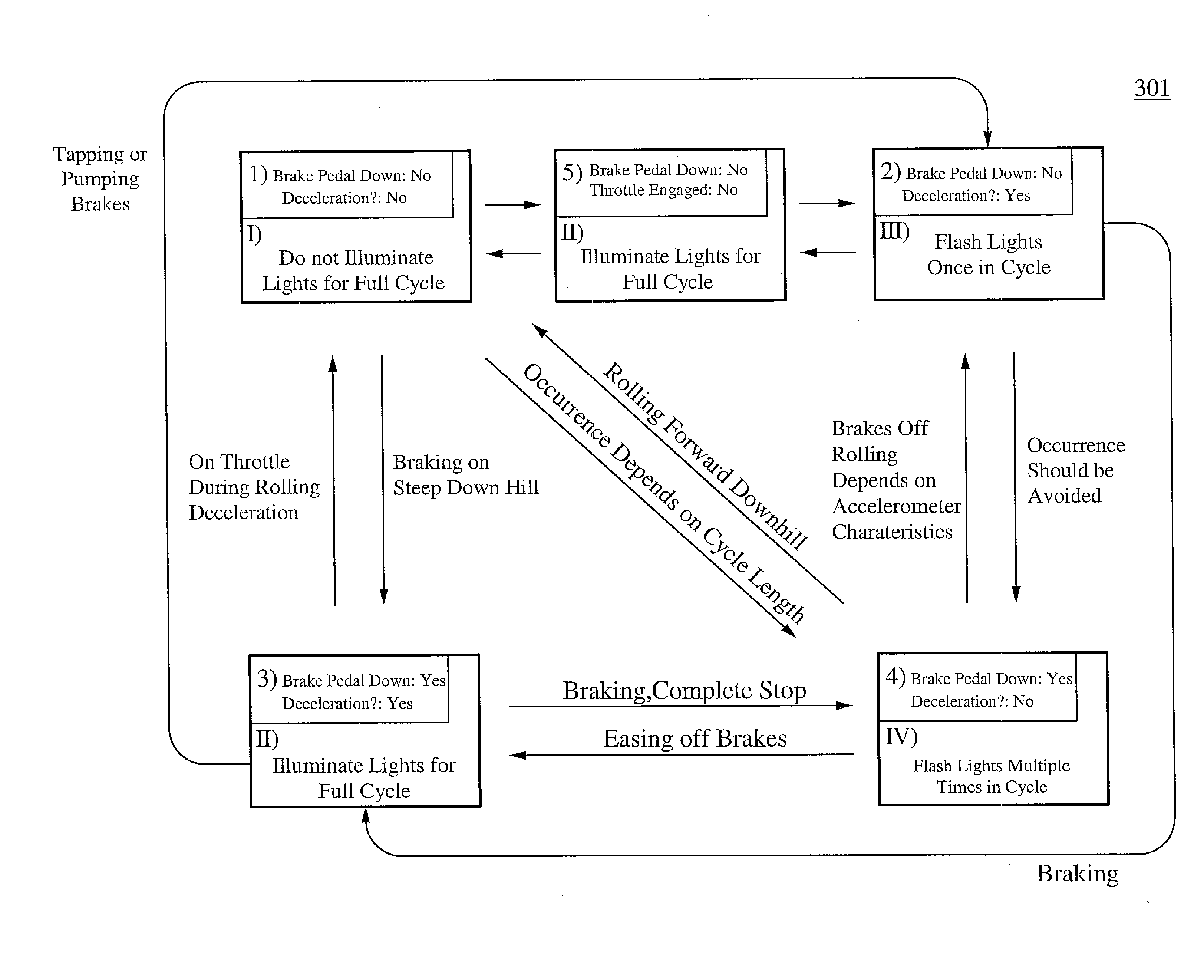
[0053]FIG. 3A is a schematic view illustrating the components of the rear-end collision avoidance system 300, warning drivers of a subject vehicle's deceleration, in accordance with one embodiment of the present invention. The rear-end collision avoidance system 300 comprises an accelerometer-gyroscopic sensor 310, a braking system engagement detector 320, a throttle engagement detector 330, and a control device 340. The accelerometer-gyroscopic sensor 310 is coupled to the control device 340, detects an absolute longitudinal deceleration of the vehicle, and sends a signal to the control device 340. The braking system engagement detector 320 is also coupled to the control device 340, detects any engagement of the braking system of the vehicle, and sends a signal to the control device 340. The throttle engagement detector 330 is also coupled to the control device 340 and detects engagement of the throttle. In alternative embodiments, the present invention ...

example 2

Anti-Rollover Systems

[0109]In some embodiments of this invention, outputs from the sensing of absolute lateral acceleration are used to adjust suspension systems by stiffening outside suspension and / or loosening inside suspension of moving vehicles. Further, in some other embodiments, simple lateral acceleration is used to adjust suspension systems during turning.

[0110]When lateral acceleration or force is applied to a vehicle, it tends to lean in the direction opposite to the force being applied, due in part to the softness of their suspension systems. This moves the center of gravity further off center and in some cases outside of their wheelbase approaching the critical rollover point. Stiffening the outside suspension and / or loosening the inside suspension keeps the center of gravity of vehicles within a tighter envelope relative to the wheelbase. This inversely affects the propensity, especially in high center of gravity loaded vehicles, to rollover when the center of gravity o...

example 3

Performance Monitoring Systems

[0115]Due to fuel efficiency goals and competitive pressures late model vehicles have the ability to monitor engine system performance through an array of sensors and detectors. The absolute accelerometer / gyroscope combination provides the ability to communicate actual power-to-the-ground data for use in engine / vehicle performance computations. In this embodiment, the accelerometer-gyroscopic sensor continuously sums absolute acceleration values to provide both absolute acceleration and actual speed values, which can be used by a manufacturers vehicle computer unit (VCU).

[0116]For example, the system 500 shown in FIG. 5 includes the accelerometer-gyroscopic sensor 510, which delivers actual speed data and absolute acceleration data to a vehicle computer unit (VCU) 520 (or at least the engine monitoring portion thereof). The VCU 520 uses baseline engine performance data 540 to either self-correct through a feedback mechanism, or to issue a warning throug...


PUM


Abstract

A communication system for a vehicle comprises a receiver to receive a signal corresponding to a traveling speed of a lead vehicle, a response device that generates an alert to warn of a change in the traveling speed of the lead vehicle, and a control device coupled to the receiver and the response device, wherein the receiver sends a signal to the control device corresponding to the traveling speed of the lead vehicle and the control device operates the response device in a manner dependent on the traveling speed of the lead vehicle. In some embodiments, the signal comprises one or more of infrared, radio frequency, wireless, WiFi, and Bluetooth®. In some embodiments, the communication system further comprises a speed control system coupled to the control device, wherein the control device operates the speed control system in a manner dependent on the traveling speed of the lead vehicle.

Description

RELATED APPLICATION[0001]This patent application is a continuation-in-part of the U.S. patent application Ser. No. 12 / 464,601, filed May 12, 2009, and entitled “ABSOLUTE ACCELERATION SENSOR FOR USE WITHIN MOVING VEHICLES,” which is hereby incorporated by reference in its entirety, which is a continuation-in-part of the U.S. patent application Ser. No. 12 / 434,577, filed May 1, 2009, and entitled “ABSOLUTE ACCELERATION SENSOR FOR USE WITHIN MOVING VEHICLES,” which is hereby incorporated by reference in its entirety, which is a continuation of the co-pending U.S. patent application Ser. No. 11 / 585,401, filed Oct. 23, 2006 and entitled, “ABSOLUTE ACCELERATION SENSOR FOR USE WITHIN MOVING VEHICLES,” now issued as U.S. Pat. No. 7,529,609, which is hereby incorporated by reference in its entirety, and which is a continuation-in-part of U.S. patent application Ser. No. 11 / 243,364, filed Oct. 3, 2005 and entitled, “ABSOLUTE ACCELERATION SENSOR FOR USE WITHIN MOVING VEHICLES”, now issued as U...

Claims


Application Information

Patent Timeline
IPC IPC(8): G06F19/00B60T7/12G08G1/09
CPCB60G2400/104B60Q1/447B60W2550/408B60W2050/008B60W2550/302B60W30/143B60W2554/804B60W2556/65B60W2050/0075B60Q1/26
Inventor BRAUNBERGER, ALFRED S.BRAUNBERGER, BEAU M.
Owner VISION WORKS IP CORP
Why Eureka
Try Eureka