Control device of reducing agent supply apparatus, reducing agent collection method, and exhaust gas purification apparatus

a technology of reducing agent and control device, which is applied in mechanical equipment, machines/engines, electric control of exhaust treatment, etc., can solve the problems of insufficient reduction and purification of the no/sub>x /sub>in the reducing catalyst, insufficient supply of reducing agent into the exhaust gas passageway, and frozen urea solution, etc., to achieve sufficient reduction of reducing agent supply path, reducing agent, and reducing the effect of reducing agen

Inactive Publication Date: 2011-01-06
BOSCH CORP
View PDF7 Cites 33 Cited by
  • Summary
  • Abstract
  • Description
  • Claims
  • Application Information

AI Technical Summary

Benefits of technology

[0013]According to the control device of the reducing agent supply apparatus of the invention, since the reducing agent injection valve is controlled to be closed when the reducing agent collecting means starts operating and to be opened when the predetermined time period elapses, the reducing agent injection valve is opened in a state in which the pressure inside the reducing agent supply paths is sufficiently lowered. Therefore, leakage of the reducing agent from the reducing agent injection valve into the exhaust gas passageway is decreased, crystallization of the reducing agent inside the exhaust gas passageway and moistening of the reducing catalyst by the reducing agent are prevented, and the wasteful consumption of the reducing agent is curbed.
[0014]Further, in the control device of the reducing agent supply apparatus of the invention, as the timing of opening the reducing agent injection valve is delayed, the reducing agent injection valve is opened after it is confirmed that the pressure inside the reducing agent supply paths is lowered, since an injection valve control portion opens the reducing agent injection valve only after the pressure inside the reducing agent supply paths becomes equal to or less than a standard value.
[0015]Further, in the control device of the reducing agent supply apparatus of the invention, as the timing of opening the reducing agent injection valve is delayed, even when a pressure sensor is not used, the reducing agent injection valve is opened in a state in which the pressure inside the reducing agent supply paths is sufficiently lowered, since the injection valve control portion opens the reducing agent injection valve only after an elapsed time period after the reducing agent collecting means starts operating exceeds a standard time period.
[0016]Further, according to the reducing agent collection method of the invention, since the reducing agent injection valve is controlled to be closed when the reducing agent collecting means starts operating and to be opened when the predetermined time period elapses, the reducing agent injection valve is opened in a state in which the pressure inside the reducing agent supply paths is sufficiently lowered. Therefore, leakage of the reducing agent from the reducing agent injection valve into the exhaust gas passageway is decreased, crystallization of the reducing agent inside the exhaust gas passageway and moistening of the reducing catalyst by the reducing agent are prevented, and the wasteful consumption of the reducing agent is curbed.
[0017]Further, according to the exhaust gas purification apparatus of the invention, the reducing agent inside the reducing agent supply paths is collected into the storage tank without the reducing agent leaking into the exhaust gas passageway when the internal combustion engine stops. Therefore, crystallization of the reducing agent inside the exhaust gas passageway and moistening of the reducing catalyst by the reducing agent are prevented, the exhaust gas purification efficiency degradation is presented, and the wasteful consumption of the reducing agent is curbed.

Problems solved by technology

Further, there is also a possibility that the urea aqueous solution becomes frozen when it is cold.
When the reducing agent solidifies inside reducing agent supply paths, a supply of the reducing agent into an exhaust gas passageway becomes insufficient, and reduction and purification of the NOx in the reducing catalyst do not progress sufficiently.
Thus, there is a concern that unpurified NOx may be discharged into the air.

Method used


Image

  • Control device of reducing agent supply apparatus, reducing agent collection method, and exhaust gas purification apparatus
  • Control device of reducing agent supply apparatus, reducing agent collection method, and exhaust gas purification apparatus
  • Control device of reducing agent supply apparatus, reducing agent collection method, and exhaust gas purification apparatus

Examples


first embodiment

[0028]An exhaust gas purification apparatus according to a first embodiment of the invention is an exhaust gas purification apparatus in which a reducing agent injection valve is controlled to be opened when a pressure value inside reducing agent supply paths is equal to or less than a predetermined standard value, the pressure value inside the reducing agent supply paths being compared with the predetermined standard value after start of operation of reducing agent collecting means.

1. Overall Structure of Exhaust Gas Purification Apparatus

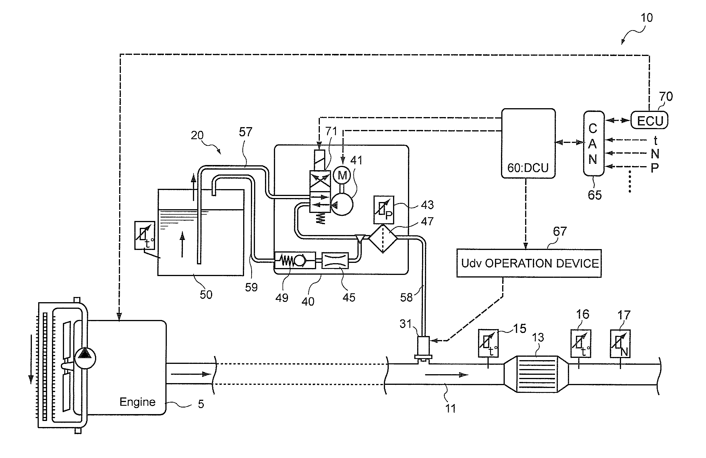
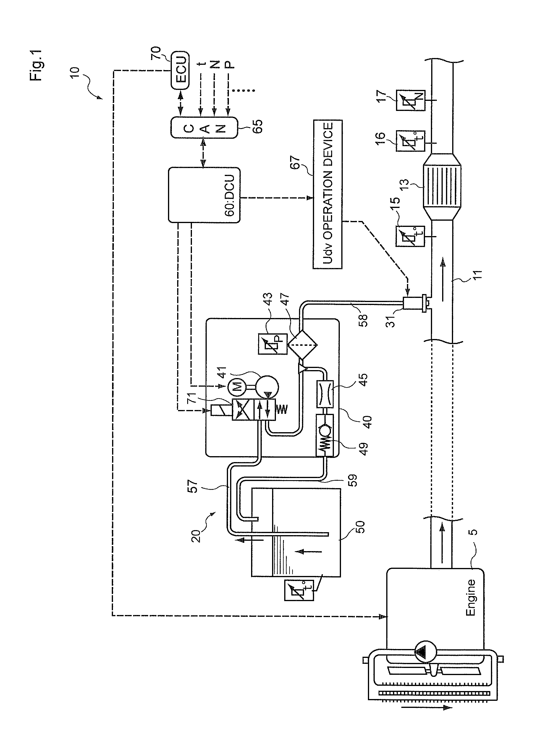
[0029]First, an example of an overall structure of the exhaust gas purification apparatus according to the embodiment will be described with reference to FIG. 1.

[0030]An exhaust gas purification apparatus 10 shown in FIG. 1 is an exhaust gas purification apparatus in which urea aqueous solution is used as a reducing agent, and after mixing and dispersing the reducing agent into exhaust gas, NOx in the exhaust gas is selectively reduced by passing ...

second embodiment

[0065]While the exhaust gas purification apparatus of the first embodiment uses the pressure value of the second supply path as a material to determine the timing of opening the reducing agent injection valve, an exhaust gas purification apparatus according to a second embodiment of the invention determines the timing of opening the reducing agent injection valve based on an elapsed time period from the start of the collection control. In this regard, the second embodiment is different from the exhaust gas purification apparatus according to the first embodiment. Explanations regarding common points with the first embodiment will be omitted, and different points from the first embodiment will be mainly explained below.

1. Control Device (DCU) of Reducing Agent Injection Valve

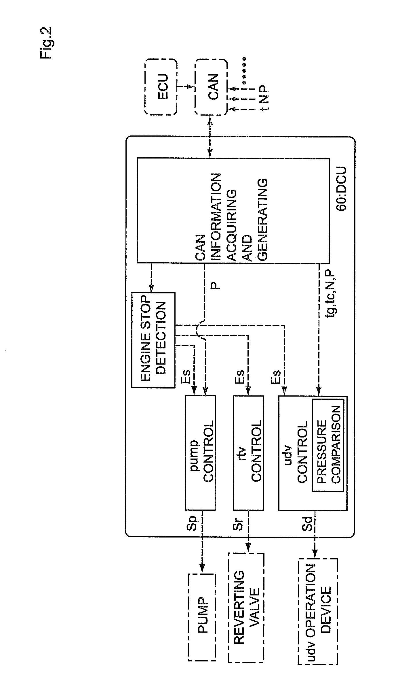
[0066]FIG. 5 is a diagram showing a structure of a DCU 160 provided in the exhaust gas purification apparatus according to the embodiment. The DCU 160 has a structure in which the elapsed time period is timed by ...


PUM


Abstract

A control device of a reducing agent supply apparatus, a reducing agent collection method, and an exhaust gas purification apparatus are provided, which can inhibit a reducing agent from leaking into an exhaust gas passageway, when performing control of collection of the reducing agent inside reducing agent supply paths.
A control device for a reducing agent supply apparatus for controlling the reducing agent supply apparatus having reducing agent collecting means for collecting a reducing agent inside reducing agent supply paths in an exhaust gas purification apparatus that adds the reducing agent to an exhaust gas upstream side of a reducing catalyst disposed inside an exhaust gas passageway of an internal combustion engine, and reduces and purifies nitrogen oxides contained in exhaust gas using the reducing catalyst, includes: a stop detection portion that detects when the internal combustion engine stops; a reducing agent collecting means control portion that starts collection of the reducing agent inside the reducing agent supply paths when the internal combustion engine stops; and an injection valve control portion that keeps a reducing agent injection valve closed when the reducing agent collecting means starts operating and opens the reducing agent injection valve after a predetermined time period elapses.

Description

TECHNICAL FIELD[0001]The present invention relates to a control device of a reducing agent supply apparatus, a reducing agent collection method, and an exhaust gas purification apparatus. The invention particularly relates to a control device of a reducing agent supply apparatus that includes reducing agent collecting means for collecting a reducing agent inside reducing agent supply paths, a reducing agent collection method, and an exhaust gas purification apparatus that includes the control device.BACKGROUND ART[0002]In exhaust gas discharged from an internal combustion engine such as a diesel engine, nitrogen oxides (hereinafter referred to as “NOx”) that may affect the environment are included. In known art, as an exhaust gas purification apparatus used for purifying the NOx, a SCR (Selective Catalytic Reduction) system is known. The SCR system adds a reducing agent, such as urea aqueous solution, into the exhaust gas, and selectively reduces and purifies the NOx in a reducing c...

Claims


Application Information

Patent Timeline
Patent Type & Authority Applications(United States)
IPC IPC(8): F01N9/00F01N3/20
CPCF01N3/2066Y02T10/24F01N2610/1473F01N2610/02Y02T10/12
Inventor KASAHARA, HIROYUKI
Owner BOSCH CORP
Why Eureka
Try Eureka