Remote level gauge adapted for liquid fuel tank

a technology of liquid fuel tank and remote level gauge, which is applied in the direction of liquid/fluent solid measurement, instruments, machines/engines, etc., can solve the problems of relatively high cost of system components used for measuring fuel level, and achieve the effect of saving battery li

Inactive Publication Date: 2011-01-06
KRITLOW MARK +1
View PDF14 Cites 31 Cited by
  • Summary
  • Abstract
  • Description
  • Claims
  • Application Information

AI Technical Summary

Benefits of technology

[0010]In more particular aspects, the fluid level reports can be delayed until periods of (a) significantly less change in fluid level, or (b) a detected reduction in continuous use. This reporting scheme can save battery life as it does not require clocks or periodic check while remaining responsive to actual demand.

Problems solved by technology

However, the system components used for measuring the fuel level have to date been relatively expensive.

Method used


Image

  • Remote level gauge adapted for liquid fuel tank
  • Remote level gauge adapted for liquid fuel tank
  • Remote level gauge adapted for liquid fuel tank

Examples


Embodiment Construction

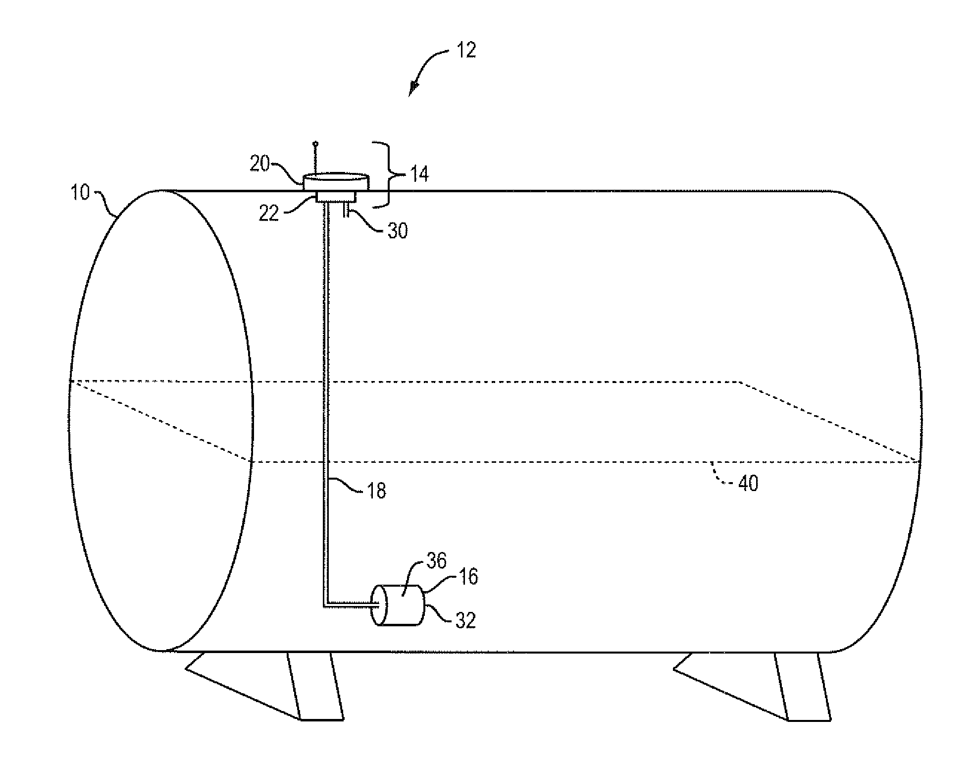
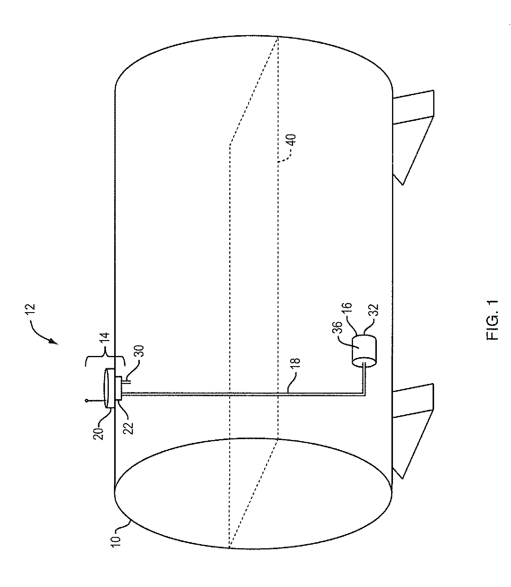
[0018]FIG. 1 is a schematic view of a fluid storage tank. The fluid storage tank may be, by way of a non-limiting example, a domestic fuel oil tank installed inside a residence. As another example, the fluid tank may be used for storing waste liquids in bulk, such as at a manufacturing plant. In pertinent portions a remote wireless fluid level sensor 12 is fitted to the tank and consists of an upper portion 14, a lower portion 16, and a cable 18 connecting the upper 14 and lower 16 portions. The upper portion 14 consists of an electronics subassembly 20 and threaded carrier 22. Electronics subassembly 20 includes a cellular mobile or other wireless data transmitter, a power source and a microprocessor (not shown in detail). The sensor 12 may be inexpensive enough to be disposable.

[0019]The power source may be one or more direct current batteries that are easily and inexpensively replaced.

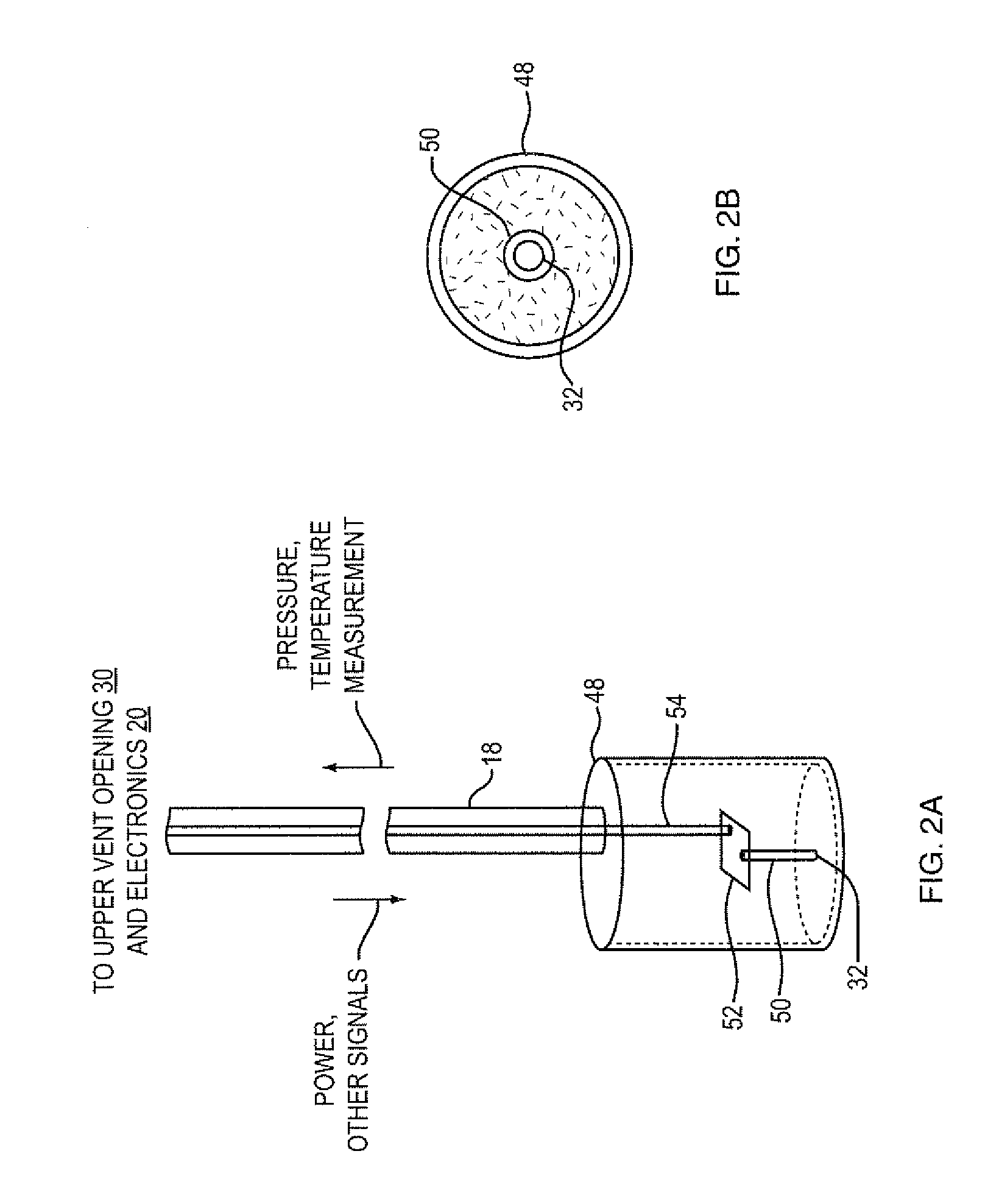
[0020]The microprocessor controls the radio equipment and receives pressure sensor signals, or p...


PUM


Abstract

An apparatus for sensing a fluid level that, in one embodiment, is adapted to fit the threads of a fill pipe or vent cap in a storage tank. A first (or upper) part of the assembly is secured in an upper portion of the tank (such as is provided at a threaded vent opening) and includes components to permit sensing pressure at a first location. A second (lower) portion of the assembly sensing pressure at a second location is disposed in a weighted casing. The second portion is coupled to the first portion through a cable that carries a section of tubing. Circuitry disposed in the second portion receives a pressure indication from the upper portion through the tubing, and detects a fluid pressure at both the upper and lower portion of the tank. The difference between the two pressures is indicative of fluid level. This level is then sent back up to the electronics assembly in the first (upper) portion. The electronics assembly can contain a microprocessor and a radio transmitter, such as a cellular or other wireless data network transmitter, to report the fluid level to a remote station such as operated by a fuel supplier. In more particular aspects, the reports of fluid levels can be delayed until periods of significantly less change in fluid level or an indication that use of the tank as stopped, to save battery life.

Description

BACKGROUND[0001]This patent application relates to bulk fluid tank level monitoring, and more particularly to a differential pressure sensor which can be retrofit to existing tanks.[0002]A large number of homes and businesses the store fluids in bulk on their own property prior to or after use. As one example, liquid fuels are stored in fluid tanks and are drawn down as needed for heating, cooking, hot water and other uses. Such stored fluids may include oil, natural gas, liquid propane or other fuels. In another example, businesses may store spent fluids in bulk such as lubricating oils, coolants, and other waste industrial fluids after their use.[0003]In rural and other remote areas where a pipeline system does not exist, tank trucks must travel to service the individual tank locations. There are two common arrangements by which a service company schedules visits. In a first arrangement, periodic visits are made, depending on the size of the tank and predicted utilizations of stor...

Claims


Application Information

Patent Timeline
Patent Type & Authority Applications(United States)
IPC IPC(8): G01F23/14
CPCG01F23/18
Inventor KRITLOW, MARK
Owner KRITLOW MARK
Why Eureka
Try Eureka