Spacecraft modular thermal platform

a technology for spacecraft and thermal platforms, applied in indirect heat exchangers, lighting and heating apparatus, cosmonautic components, etc., can solve the problems of difficult to use for the thermal control of an entire spacecraft, power and cost impact, and difficult to achieve the thermal control of a small spacecraft. , to achieve the effect of reducing time, expenses and resources, and discharging excess hea

Active Publication Date: 2011-01-06
IBERICA DEL ESPACIO
View PDF17 Cites 20 Cited by
  • Summary
  • Abstract
  • Description
  • Claims
  • Application Information

AI Technical Summary

Benefits of technology

[0016]The second chamber is used to regulate the temperature set-up point. This second chamber is charged with gas (for instance, argon, nitrogen) with a predetermined pressure value. This pressure is a temperature controlling factor: if the temperature of the controlled equipment is below the specified value, the corresponding saturated vapour pressure of the working fluid will be less than the pressure of the gas in the second chamber. This means that the path to the condenser will be closed and that all flow will be directed to the bypass line. As soon as the heat input grows up, the connection to the condenser (if the condenser is colder than the controlled equipment) will start to be open because the pressure in the two-phase loop system will be higher than the pressure in the second chamber. The moving element in the main chamber will self-adjust its position according to the heat load. If one of the heat rejection systems is hotter than the cooled spacecraft equipment due, for instance, to sun exposure, the remaining “dark” heat rejection systems of the SMTP will dissipate the “excess” of heat to the environment thanks to the heat flow regulator of the two-phase loop system. Such approach provides large flexibility in design of new spacecrafts and significantly reduces time, expenses and resources required for spacecraft designing, manufacturing and testing phases because standard, off-the-shelf, space qualified modular platforms will be used for the satellite onboard equipment arrangement and installation. The modular thermal platform of the invention will warranty required temperature (the set-up point of the heat flow regulator is specified by the customer) and maximum power dissipation of the equipment (SMTP) can be selected from a number of different platforms for different power levels, or by assembling several modular thermal platforms) at any possible operational / mission scenarios.

Problems solved by technology

This makes thermal control a key matter in the design and operation of a spacecraft with a significant weight, power and cost impact in the overall spacecraft budgets.
This solution can be applied on element level but it is difficult to be used for the thermal control of an entire spacecraft.
This design is very heavy and very expensive for small spacecrafts.
This makes this design very complex, not very efficient (many thermal interfaces) and not reliable.
Also, VCHP are not flexible enough and capable to transfer high power (maximum several hundreds of watts) for shorter distances (up to 2-3 m).
The problem of this system is an impossibility to control the temperature of the equipment since loop heat pipes are just heat transfer devices.
The problem of this system is connected with thermal design complexity: two opposite radiators have to be well thermally disconnected but it is difficult to reach this aim since one radiator with embedded heat exchanger is placed on the top of another.
Therefore, the thermal control system of JP 2001315700 is not capable of providing good temperature stabilization in a narrow range (several degrees).
Also, although this system is a passive thermal control system but heaters and control electronics require devoted power budget, which is a critical issue for space applications.
The thermal switches in U.S. Pat. No. 6,073,888 are operating as ON / OFF devices: such type of control is not precise and sensitive enough for thermal systems, where thermal inertia plays an important role.

Method used


Image

  • Spacecraft modular thermal platform
  • Spacecraft modular thermal platform
  • Spacecraft modular thermal platform

Examples


Embodiment Construction

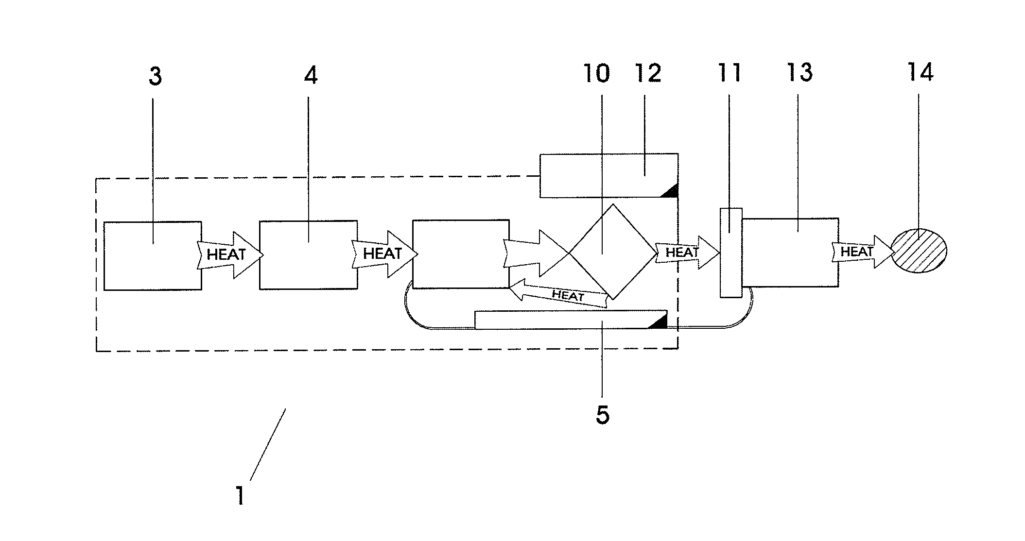
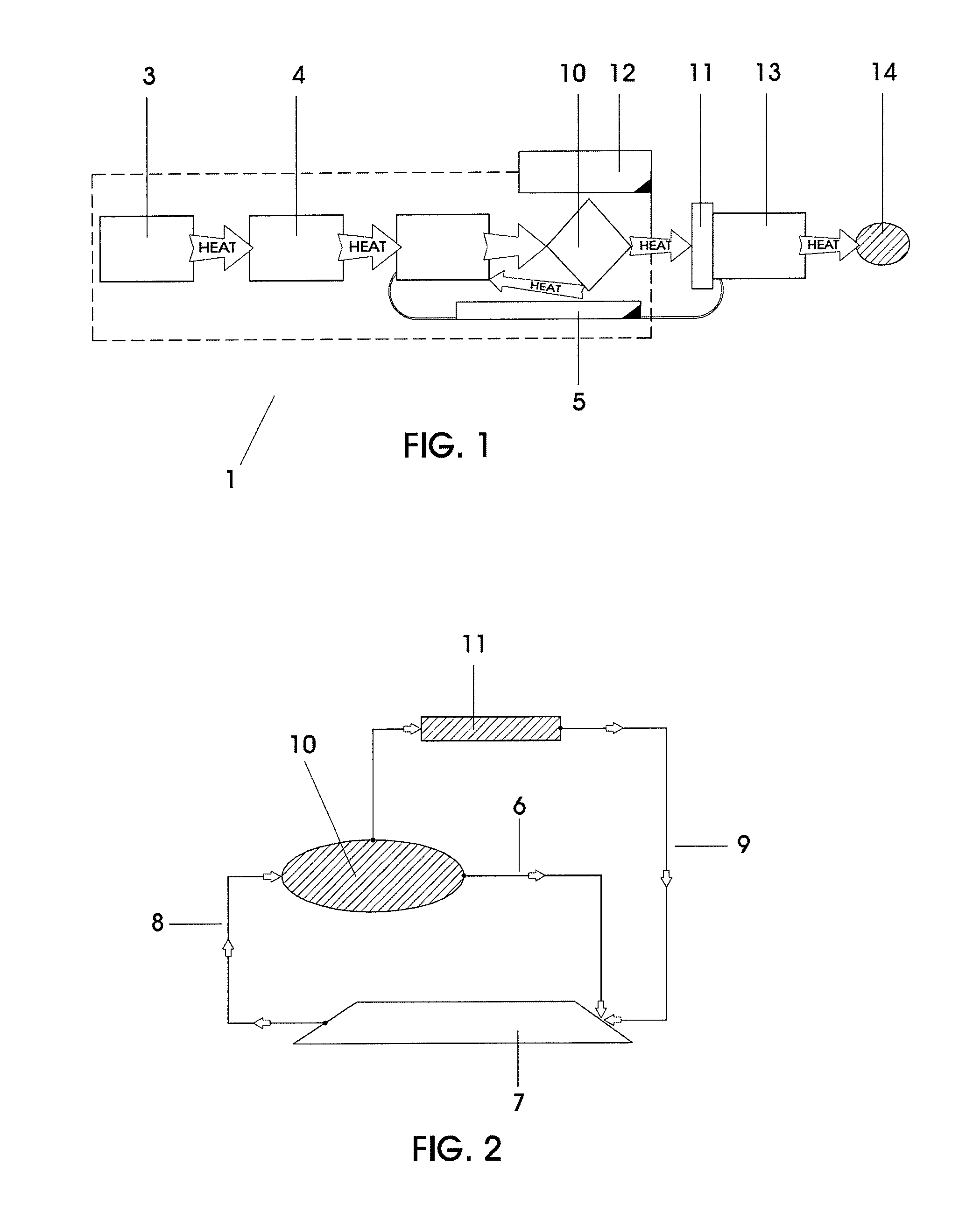
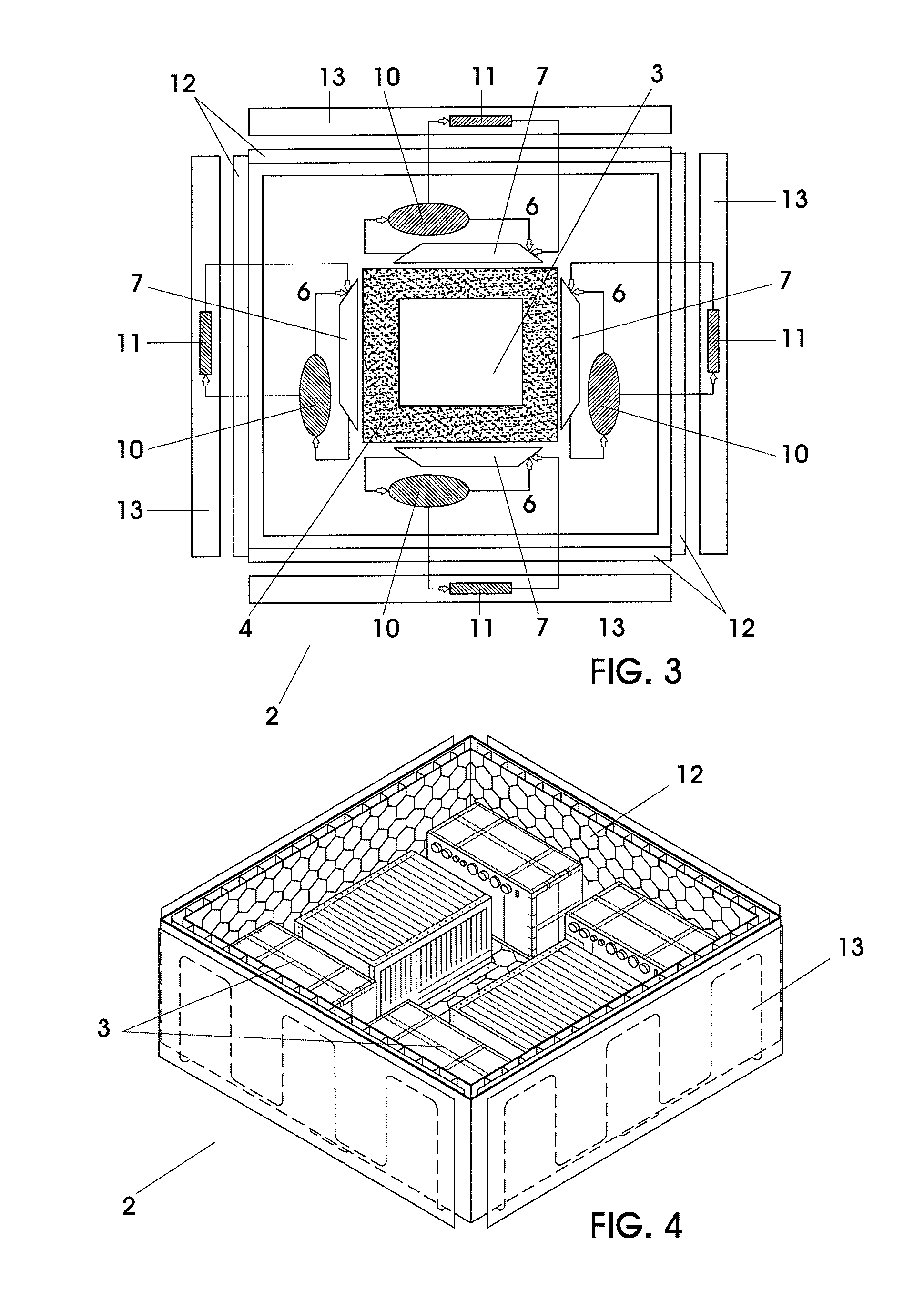
[0034]The invention is therefore intended to provide a spacecraft modular thermal platform 2 (SMTP) (FIG. 3) for controlling the thermal loads coming from a heat source 3, this platform 2 being modular and comprising at least one thermal module 1 (TM) (FIG. 1). The thermal module 1 comprises the following elements:[0035]at least one heat source 3, typically comprising onboard electronic equipment;[0036]a two-phase (liquid and vapor) loop system with a bypass line (TPBL) 5, comprising:[0037]a bypass line 6[0038]a thermal collector 7, preferably an evaporator[0039]transport lines 8, 9 for the two phases, vapor and liquid[0040]a heat flow regulator 10, preferably a pressure regulating valve[0041]a condenser 11;[0042]a thermal insulation system 12, such as Multi Layer Insulation (MLI);[0043]a heat rejection system 13, preferably comprising a radiator, and[0044]a heat sink 14, typically the space.

[0045]The thermal module 1 can also comprise an isothermalization system 4, this system 4 pr...


PUM


Abstract

Thermal module (1) for use on a spacecraft to control thermal loads coming from a heat source (3) comprising a two-phase loop system (5) and a heat rejection system (13), the two-phase loop system (5) comprising a thermal collector (7), a heat flow regulator (10), a by-pass line (6) and a condenser (11), the condenser (11) and the heat rejection system (13) being thermally coupled, such that the heat flow regulator (10) of the two-phase loop system (5) redirects part of the thermal loads from the heat source (3) to the condenser (11), from which the heat rejection system (13) directs said thermal loads to a heat sink (14), the temperature of the heat source (3) being regulated by bypassing another part of the thermal loads back to the thermal collector (7) through the by-pass line (6) in a proportional manner, to avoid the heat source (3) overcooling, being the heat rejection system (13) designed based on the hottest possible conditions for the spacecraft mission.

Description

FIELD OF THE INVENTION[0001]The present invention relates to a platform for controlling thermal loads, particularly for use on a spacecraft.BACKGROUND OF THE INVENTION[0002]Most of the components and subsystems of a spacecraft must operate in restricted temperature ranges. This makes thermal control a key matter in the design and operation of a spacecraft with a significant weight, power and cost impact in the overall spacecraft budgets.[0003]Spacecraft thermal control relies on the global spacecraft thermal balance: the heat loads must be rejected to deep space that works as a thermal sink. Since no matter links this sink and the spacecraft, this rejection is made by thermal radiation through dedicated radiators installed on the satellite external surfaces.[0004]Spacecraft thermal loads come from the internal spacecraft equipment dissipation and, externally, from the sun and the earth or from the celestial bodies around which the spacecraft orbits. The thermal systems used in space...

Claims


Application Information

Patent Timeline
Patent Type & Authority Applications(United States)
IPC IPC(8): B64G1/52
CPCB64G1/50B64G1/503B64G1/506F28F2250/06F28D15/043F28D15/06F28D15/0266
Inventor TORRES SEPULVEDA, ALEJANDROMISHKINIS, DONATASPASTOR FERNANDEZ, JOSE LUIS
Owner IBERICA DEL ESPACIO
Why Eureka
Try Eureka