Method and System for Highlighting an Image Representative of a Flight Parameter of an Aircraft

Active Publication Date: 2011-01-06
INNOVATIVE SOLUTIONS & SUPPORT
View PDF20 Cites 41 Cited by
  • Summary
  • Abstract
  • Description
  • Claims
  • Application Information

AI Technical Summary

Benefits of technology

[0013]As a result of the enlarged size of the displayed data or graphic, in many embodiments, the pilot can more easily view and enter or modify or select the new data setting. The attention of the pilot that must be directed to assuring an accurate manual adjustment of the data setting is thereby reduced, in some embodiments, relative to the other tasks and operations and work load to which the pilot must also devote his or her attention.
[0014]In a further aspect of some embodiments of the invention, the setting being input or adjusted may instead or additionally be displayed, on the FPD, in the enlarged condition, on a graphical scale or in another manner that indicates to the viewer the new data setting value being input relative to the range of values to which the setting may be adjusted. For example, when the local barometric pressure setting is to be input or adjusted to 30.22 in. Hg, an enlarged graphical scale may be displayed on the FPD in some embodiments, and, upon entry or adjustment or selection of the pressure value 30.22, the display may graphically show that a value approximately midway along the scale, a relatively small amount greater than the “standard” barometric pressure of 29.92 in. Hg, has been entered or selected, for example. In various embodiments, this permits the pilot to quickly and easily verify that the correct and intended setting has been entered—first, by providing an enlarged, graphical display that enhances the pilot's awareness of the scale for the relevant data and of the particular value (in relation to that displayed scale) that has been set through the use of an intuitive graphical representation, and second, in some embodiments, by therefore not requiring that the pilot divert undue attention from other ongoing efforts or activities or needs in the aircraft cockpit or flight deck. The pilot's attention may thus be quickly and accurately drawn to that location on the FPD screen at which the data entry is to be effect, and/or at which the current and/or new data value is shown, in many embodiments, thereby minimizing the amount of time required to complete the data setting or adjustment procedure or operation, as examples.
[0015]The event trigger or initiator of the enlargement in size (and of the optional graphical or other scale-like depiction of the setting value range) of the relevant data on the FPD can, in accordance with some embodiments of the invention, be implemented in a suitable manner, and, in some cases, as may be or be deemed appropriate for or dictated by the particular manner in which the setting adjustment is manually e

Problems solved by technology

Because the numeric indications on the index scale are quite small and the consequences of an incorrect setting can be disastrous in certain situations, an unusual amount of pilot attention must be directed to the instrument when setting, or resetting, the altimeter adjustment.
The potential for introducing inadvertent errors into the adjustment is understandably greater in flight, when the attention required to correctly effect the adjustment must come at the expense of the pilot's other responsibilities and workload in maintaining situational awareness and otherwise operating and controlling the aircraft.
This problem is especially apparent in multipurpose FPDs that concurrently display numerous different types of information and data to the aircraft pilot, thereby increasing the opportunity for a busy or task-overloaded pilot to inadvertently manipulate the wrong knob or control and/or to view the wrong onscreen data in ent

Method used


Image

  • Method and System for Highlighting an Image Representative of a Flight Parameter of an Aircraft
  • Method and System for Highlighting an Image Representative of a Flight Parameter of an Aircraft
  • Method and System for Highlighting an Image Representative of a Flight Parameter of an Aircraft

Examples


Embodiment Construction

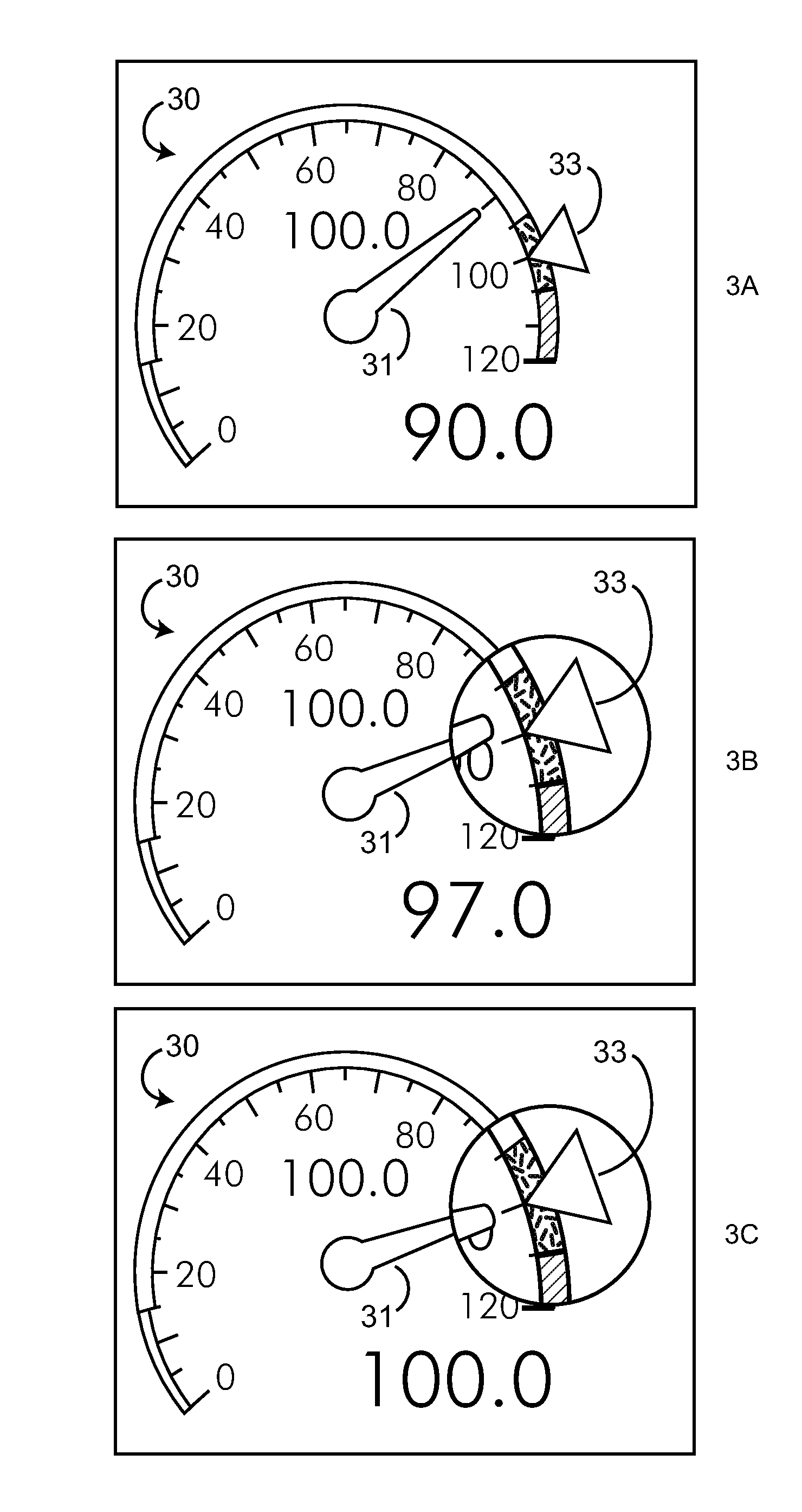
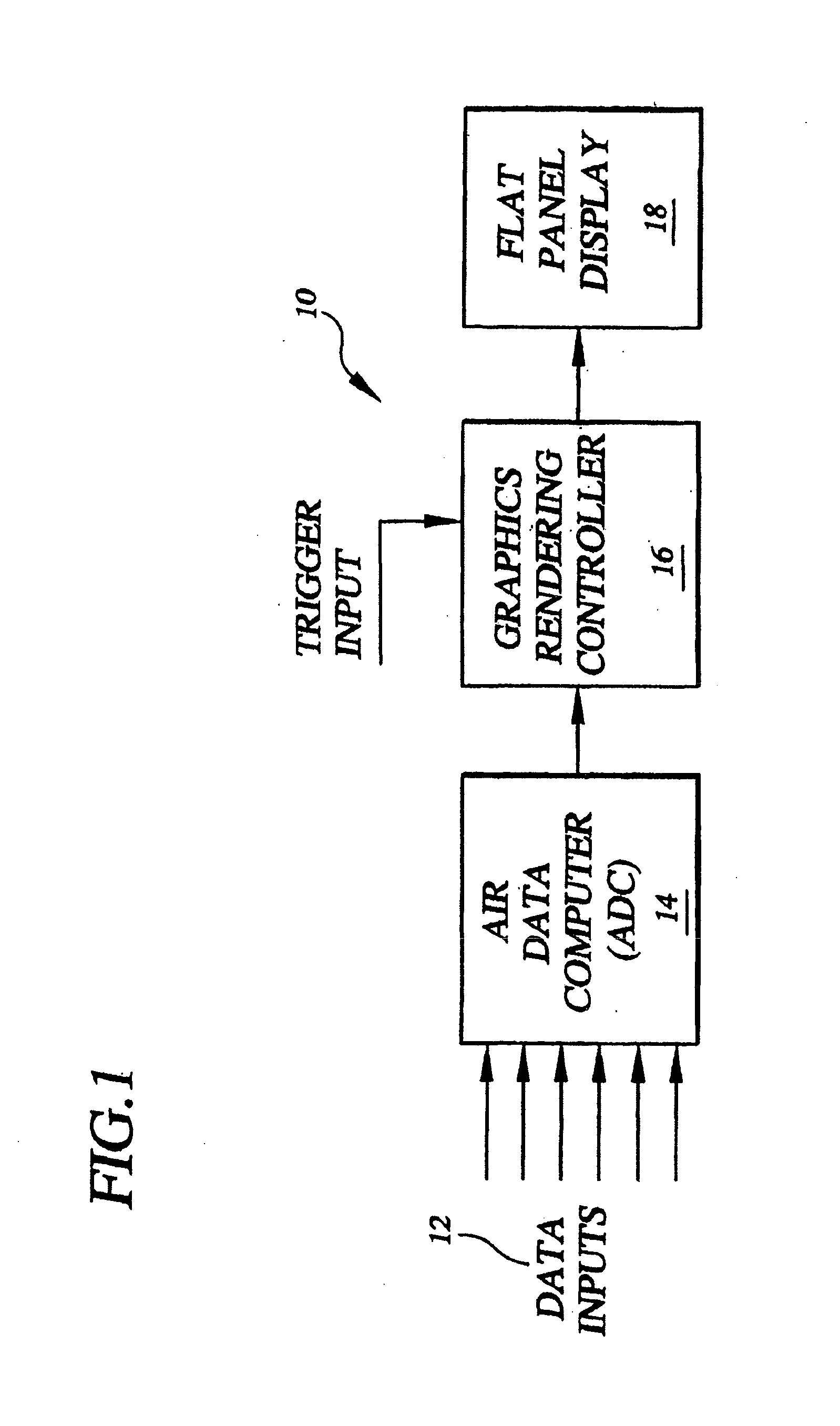
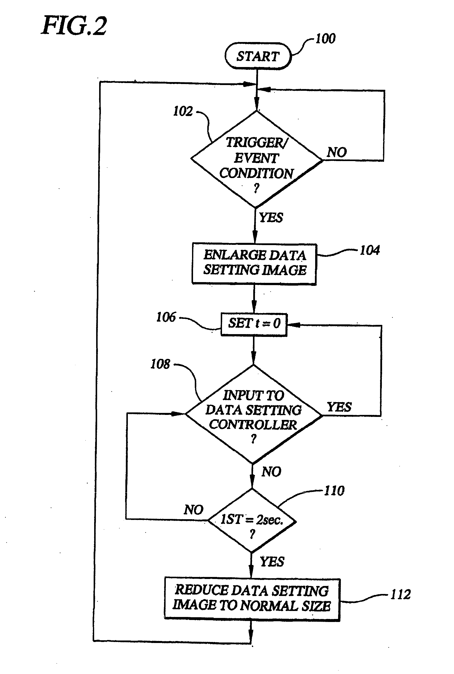
[0010]In various embodiments, the invention provides methods, systems, and apparatuses for facilitating the manual adjustment or entry of data settings—such, by way of illustrative example, as the current local barometric pressure—in an aircraft cockpit or flight deck environment in which the data is digitally displayed on a flat panel display (FPD), such for example as a liquid crystal, display (LCD). In some embodiments, for example, the invention is equally applicable to a FPD that displays only the particular data or setting or information of interest—such as a dedicated, single-function digital FPD or LCD altimeter—as well as to a FPD that is operable to concurrently display a multiplicity of data or settings or information, among them the particular data or setting or information with respect to which the manual adjustment or setting is required. In some embodiments, the invention may also be applied to the setting of user-adjustable data that is not normally displayed or depi...


PUM


Abstract

A method and system for highlighting a parameter image representative of a flight parameter of an aircraft to a user in a multi-parameter aircraft instrument display, such as a flat panel display. An electronic instrument display is configured to present parameter images, at least one of which includes a first indicator configured to indicate a specific value (e.g., a target value) for a flight parameter and a second indicator configured to indicate an actual flight parameter value that changes according to variations in the flight parameter. A graphics rendering controller is configured to generate the parameter images and to enlarge a portion of the parameter image when the actual flight parameter value is within a predetermined range from the target value.

Description

CROSS-REFERENCE TO RELATED APPLICATION[0001]This application is a continuation-in-part of commonly owned copending U.S. patent application Ser. No. 11 / 635,135, filed Dec. 7, 2006, which is a continuation of commonly owned U.S. patent application Ser. No. 10 / 616,208, filed Jul. 8, 2003, now U.S. Pat. No. 7,346,854, which claims priority from U.S. Provisional Patent Application No. 60 / 394,591, filed Jul. 8, 2002, the contents of which applications are hereby incorporated by reference in their entirety.BACKGROUND OF THE INVENTION[0002]1. Field of the Invention[0003]The present invention is directed to the display of manually entered, computer generated or measured data on a multi-parameter aircraft instrument display, such as a flat panel display, in which there are a plurality of simultaneously displayed parameters, and more particularly to a method and system of providing easily recognizable visual confirmation to the user that the correct parameter in the multi-parameter display is ...

Claims


Application Information

Patent Timeline
IPC IPC(8): G01C23/00
CPCB60K37/02B60K2350/1072G01D7/002G06F3/04847G01C23/00G09G3/20G09G2340/0407G09G2340/045B64D45/00G06F2203/04805B64D43/00B60K2370/155B65D47/00G06F3/14
Inventor HEDRICK, GEOFFREY S.M.
Owner INNOVATIVE SOLUTIONS & SUPPORT
Why Eureka
Try Eureka