Three-dimensional shape measuring apparatus, integrated circuit, and three-dimensional shape measuring method

Inactive Publication Date: 2011-01-06
PANASONIC CORP
View PDF2 Cites 51 Cited by
  • Summary
  • Abstract
  • Description
  • Claims
  • Application Information

AI Technical Summary

Benefits of technology

[0013]With the three-dimensional shape measuring apparatus according to the present invention, it is possible to separate a real image of an object which can be captured by an image capturing unit and a virtual image of the object reflected in the mirror, when capturing images of the object by using the mirror. With this, for example, it is possible to use an image captured by a single image capturing unit as an image captured at an image capturing position different from positions at which the virtual and real images are actually captured in the real world. With this, it is possible to r

Problems solved by technology

However, since it is necessary to perform calibration on each of the cameras, there is a con

Method used


Image

  • Three-dimensional shape measuring apparatus, integrated circuit, and three-dimensional shape measuring method
  • Three-dimensional shape measuring apparatus, integrated circuit, and three-dimensional shape measuring method
  • Three-dimensional shape measuring apparatus, integrated circuit, and three-dimensional shape measuring method

Examples


Example

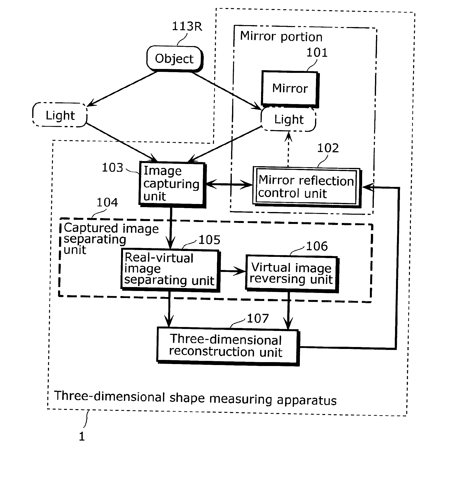
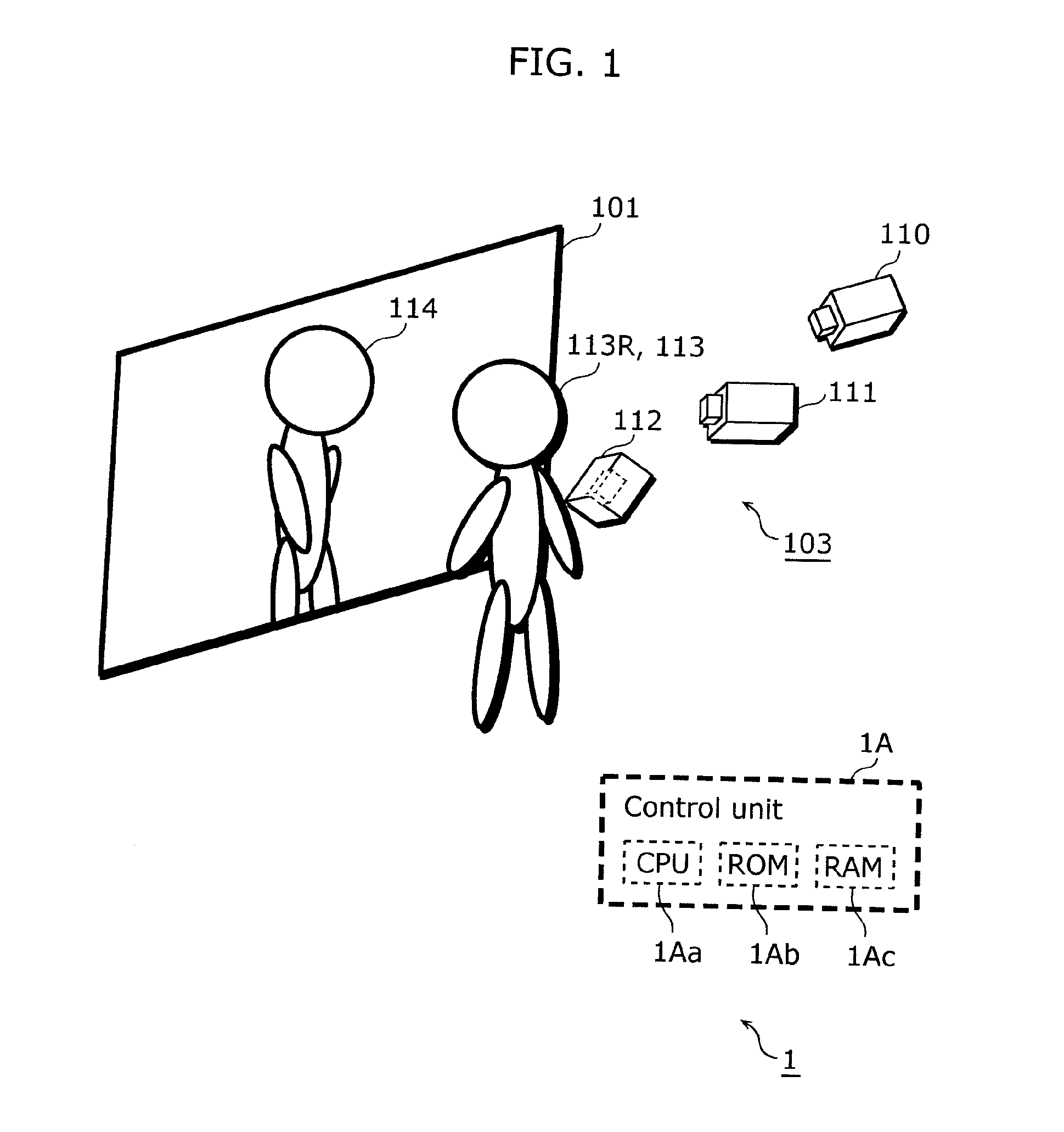
[0078]FIG. 1 is a configuration diagram showing an outline of a three-dimensional shape measuring apparatus according to a first embodiment of the present invention.

[0079]As shown in FIG. 1, a three-dimensional shape measuring apparatus 1 includes: a mirror 101, an image capturing unit 103 including image capturing apparatuses 110 to 112, and a control unit 1A.

[0080]Note that an object 113R is an object whose three-dimensional shape is measured by the three-dimensional shape measuring apparatus 1. For example, the object 113R is a user whose three-dimensional shape is measured by the three-dimensional shape measuring apparatus 1. In addition, a virtual image 114 is another virtual image which is a reflection of the object 113R reflected in the mirror 101 and appears separately from a real image 113 of the object 113R. That is, the virtual image 114 is an image of the object 113R, and is formed with light proceeding from the object 113R and reflected by the mirror 101.

[0081]The contr...

Example

[0168]FIGS. 12 and 13 are schematic views of a three-dimensional shape measuring apparatus 2 according to a second embodiment of the present invention.

[0169]FIG. 14 is a block diagram showing each portion included in the three-dimensional shape measuring apparatus 2 according to the second embodiment and a processing flow when three-dimensional reconstruction is performed using the three-dimensional shape measuring apparatus 2 according to the second embodiment of the prevent invention.

[0170]FIG. 15 is a block diagram showing a configuration of the mirror 101 and a mirror reflection control unit 132 according to the second embodiment.

[0171]FIG. 16 is a diagram showing an example of a positional relationship between: a mirror 101; a mirror shielding unit 130; a display unit 131; image capturing apparatuses 110 to 112 and virtual image capturing apparatuses 210 to 212 which correspond to the image capturing apparatuses, respectively; and a real image 113 of an object 113R and a virtua...

Example

[0193]FIGS. 17 and 18 are schematic views of a three-dimensional shape measuring apparatus 3 according to a third embodiment of the present invention.

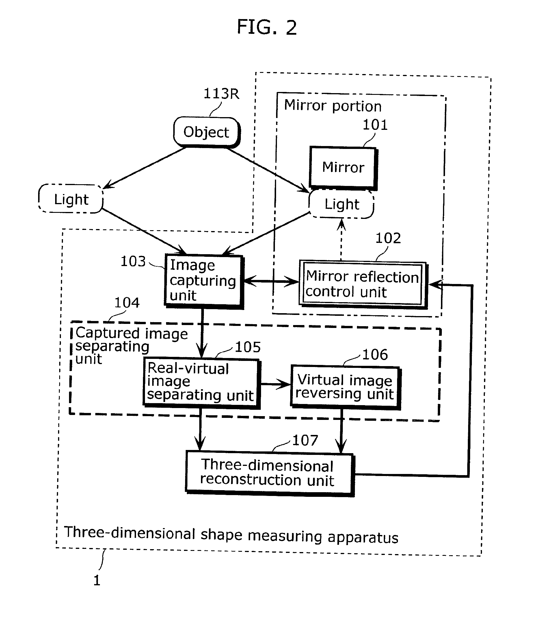
[0194]FIG. 19 is a block diagram showing a configuration of the mirror reflection control unit 142 according to the third embodiment. Note that each of the portions included in the three-dimensional shape measuring apparatus 3, except the mirror reflection control unit 142, and the block diagram showing a flow of the processing performed when the three-dimensional reconstruction is performed according to the present embodiment are the same as in the first embodiment (see FIG. 2), and therefore the detailed description thereof will be omitted.

[0195]As shown in FIGS. 17 to 19, the three-dimensional shape measuring apparatus 3 includes a light irradiation unit 140.

[0196]FIG. 20 is a diagram showing an example of a positional relationship between: a mirror 101; a light irradiation unit 140; a display unit 131; image capturing apparatuses 1...


PUM


Abstract

It is possible to perform three-dimensional shape measurement with easy processing, regardless of whether an object is moving or not. An image capturing unit (103) captures a captured image (I) including both a real image (I2) of the object (113R) and a mirror (101). A light amount changing unit (63a) changes a light amount of a virtual image (I1). An image separating unit (captured image separating unit 104) specifies, as a virtual image (Ib1), an image in a region having a different light amount (R1), in a captured image (Ia) in which the light amount is changed and a captured image (Ib) in which the light amount is not changed, and specifies an image in a region having the same light amount (R2) as a real image (Ib2). A three dimensional shape is reconstructed from the real image and so on that are specified.

Description

TECHNICAL FIELD[0001]The present invention relates to a method for performing three-dimensional measurement on an object, and an apparatus for the measurement using a mirror, based on a virtual image reflected in the mirror.BACKGROUND ART[0002]For a conventional three-dimensional shape measuring apparatus, a light-section method is used which is to: irradiate an object with a laser slit beam, capture a positional relationship of the slit beam on the object using a camera so as to measure a distance from the object, and reconstruct a three dimensional shape of the object. Another method is a volume intersection method which is to estimate an outer shape of the object by installing cameras all round the object so as to eliminate blind spots and superimposing silhouettes three-dimensionally, based on a silhouette image of the object captured by each of the cameras and the camera position.[0003]In performing three-dimensional reconstruction of the object according to the above method, t...

Claims


Application Information

Patent Timeline
IPC IPC(8): H04N13/02G06K9/20
CPCH04N13/0497G01B11/24H04N13/398
Inventor MORIYAMA, TAKAAKIUESAKI, AKIRAYOSHIDA, TADASHIISHIBASHI, YUDAI
Owner PANASONIC CORP
Why Eureka
Try Eureka