Circular tomosynthesis x-ray tube

a tomosynthesis and x-ray tube technology, applied in the direction of material analysis using wave/particle radiation, instruments, nuclear engineering, etc., can solve the problems of asymmetric image artifacts, awkward movement of x-ray sources, and expansion of acquisition time, so as to improve image quality and reduce effort

Inactive Publication Date: 2011-01-06
KONINKLIJKE PHILIPS ELECTRONICS NV
View PDF9 Cites 11 Cited by
  • Summary
  • Abstract
  • Description
  • Claims
  • Application Information

AI Technical Summary

Benefits of technology

[0005]It would be desirable to provide an improved method and device for X-ray examination being capable of providing an improved image quality at a lower effort on the device side.

Problems solved by technology

However, this is disadvantageous for several reasons.
The movement of the X-ray source is awkward and expands the acquisition time.
Moreover, the source trajectory is suboptimal, since it leads to asymmetric image artifacts owing to the time which is necessary for the movement along a circular arc or circular line.
However, such a device requires a plurality of detectors leading to a high effort on the detector side owing to the need of a plurality of detectors.

Method used


Image

  • Circular tomosynthesis x-ray tube
  • Circular tomosynthesis x-ray tube
  • Circular tomosynthesis x-ray tube

Examples


Embodiment Construction

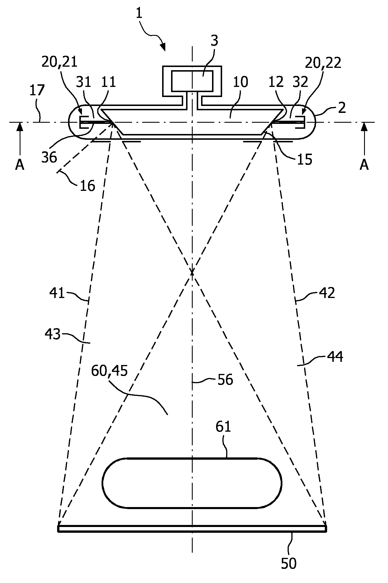
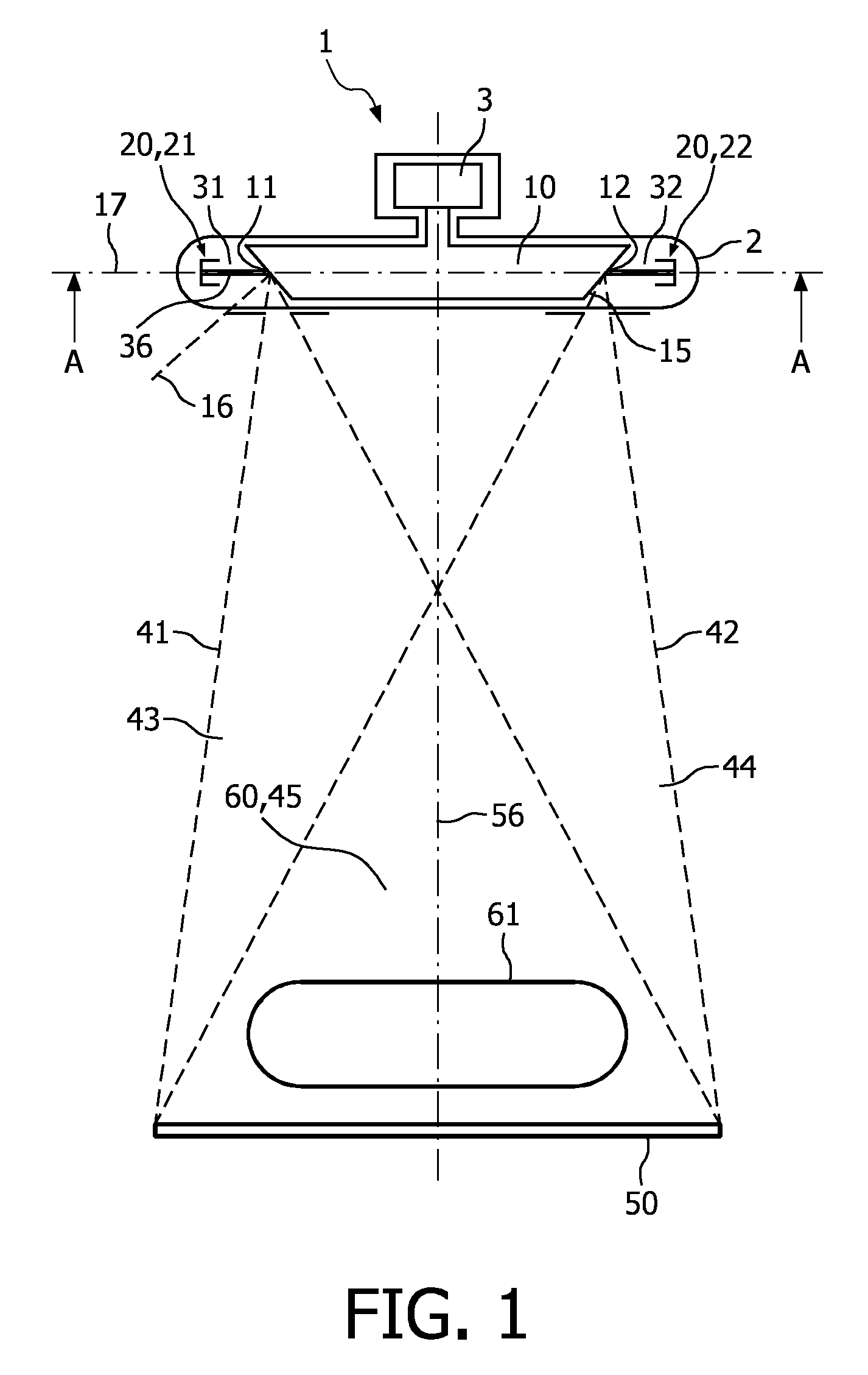
[0053]FIG. 1 illustrates an X-ray tube 1. In a housing 2 of the X-ray tube 1, there is provided an anode arrangement 10, which may be rotated by a motor 3 in order to avoid damages on the focal spot track. The anode arrangement 10 may be provided with a plurality of focal spot positions 11,12, which however, do not mandatorily correspond to fix positions on the surface of the anode, since the surface of the anode 10 may rotate during operation. The focal spot position 11,12 shall be considered as the respective position, where the electron beam 31, 32 meets the anode arrangement. It should be noted that the anode arrangement 10 may be provided also with a larger number of focal spots or focal spot positions. Within the housing 2 there is also provided a cathode arrangement 20, having a plurality of cathodes including a first cathode 21 and a second cathode 22. It should be also noted that the number of cathodes, as well as the focal spot positions, is not limited to the number of tw...


PUM


Abstract

Tomosynthesis system with a rotating anode X-ray tube enabling a circular scan trajectory, wherein the X-ray tube 1 may be equipped with a large number of cathodes (21, 22) distributed around an anode. This allows to generate X-rays (41, 42) at focal spot positions (11, 12), for example evenly distributed on a for example circular line (14) on the surface (15) of an anode (10). The object (61) may be located on the (10) axis of rotation (6) of the anode at some distance to the source. For an examination, the object (61) may be exposed to X-ray beams (41, 42) generated successively on all focal spot positions (11, 12), wherein no movement of the X-ray tube 1 is necessary. The transmitted X-ray intensities may be measured by a flat panel detector (50) to achieve a reconstructed three-dimensional image data.

Description

FIELD OF THE INVENTION[0001]The present invention relates to an X-ray tube and an X-ray examination apparatus for circular tomosynthesis and a corresponding method, and in particular to an X-ray tube and an X-ray examination apparatus being capable of providing an improved image quality and a corresponding method.BACKGROUND OF THE INVENTION[0002]Digital tomosynthesis is currently discussed as the next breast screening technique, since it yields a three-dimensional data with doses comparable to conventional mammography. In current tomosynthesis systems for mammography, the X-ray source is moved along a circular arc or a circular line around the object during a data acquisition. However, this is disadvantageous for several reasons. The movement of the X-ray source is awkward and expands the acquisition time. Moreover, the source trajectory is suboptimal, since it leads to asymmetric image artifacts owing to the time which is necessary for the movement along a circular arc or circular ...

Claims


Application Information

Patent Timeline
Patent Type & Authority Applications(United States)
IPC IPC(8): H05G1/60H01J35/06H01J35/14
CPCH01J35/065H01J35/14H01J2235/068H01J2235/066H01J2235/062H01J35/153
Inventor THRAN, AXELERHARD, KLAUS
Owner KONINKLIJKE PHILIPS ELECTRONICS NV
Why Eureka
Try Eureka