
Method for analyzing a tube system

a tube system and analysis method technology, applied in image enhancement, image data processing, instruments, etc., can solve the problems of difficult to resolve the exact vessel topology, difficult to analyze the underlying vascular structure, and difficult to solve the exact vascular topology, etc., to achieve the effect of fast and efficien

Active Publication Date: 2011-01-06
KONINKLJIJKE PHILIPS NV
View PDF23 Cites 15 Cited by
  • Summary
  • Abstract
  • Description
  • Claims
  • Application Information

AI Technical Summary

Benefits of technology

[0012]It is believed, that such a method in particular when used for treating patients may reduce the amount of a contrast agent and X-ray exposure in for example the process of angiography. This might be of general benefit for the patient, because less contrast agents mean less stress and fewer possible side effects on the patient. In clinical practice, it is tried to minimize the use of contrast agent. If it is essential for the success of the intervention even large dosages of contrast agent are applied. Afterwards a dialysis is performed to reduce the side effects of the toxic contrast agent.
[0085]It may be seen as a gist of the invention, that a flow simulation is performed on a tube system which, when e.g. applied to angiography, may allow to perform a virtual angiography without injection of a contrast agent into a patient.

Problems solved by technology

In applications such as neuro vascular or hepatovascular treatment, the treatment is often complicated by the complexity of the underlying vascular structures.
Due to strong overlap of the often small, tortuous and diseased vessels, angiographic interpretation can be a very laborious task which requires multiple contrast agent injections to visualize the vessel tree from different hierarchy levels.
Although 2D imaging is dynamic, which means that the inflow and the distribution of the injected contrast agent bolus can be surveyed, it is often impossible to resolve the exact vessel topology.
But due to the static an often unselective character of the reconstruction assessment of the hemodynamic interrelations is still a challenging task.

Method used


Image

  • Method for analyzing a tube system
  • Method for analyzing a tube system
  • Method for analyzing a tube system

Examples


Embodiment Construction

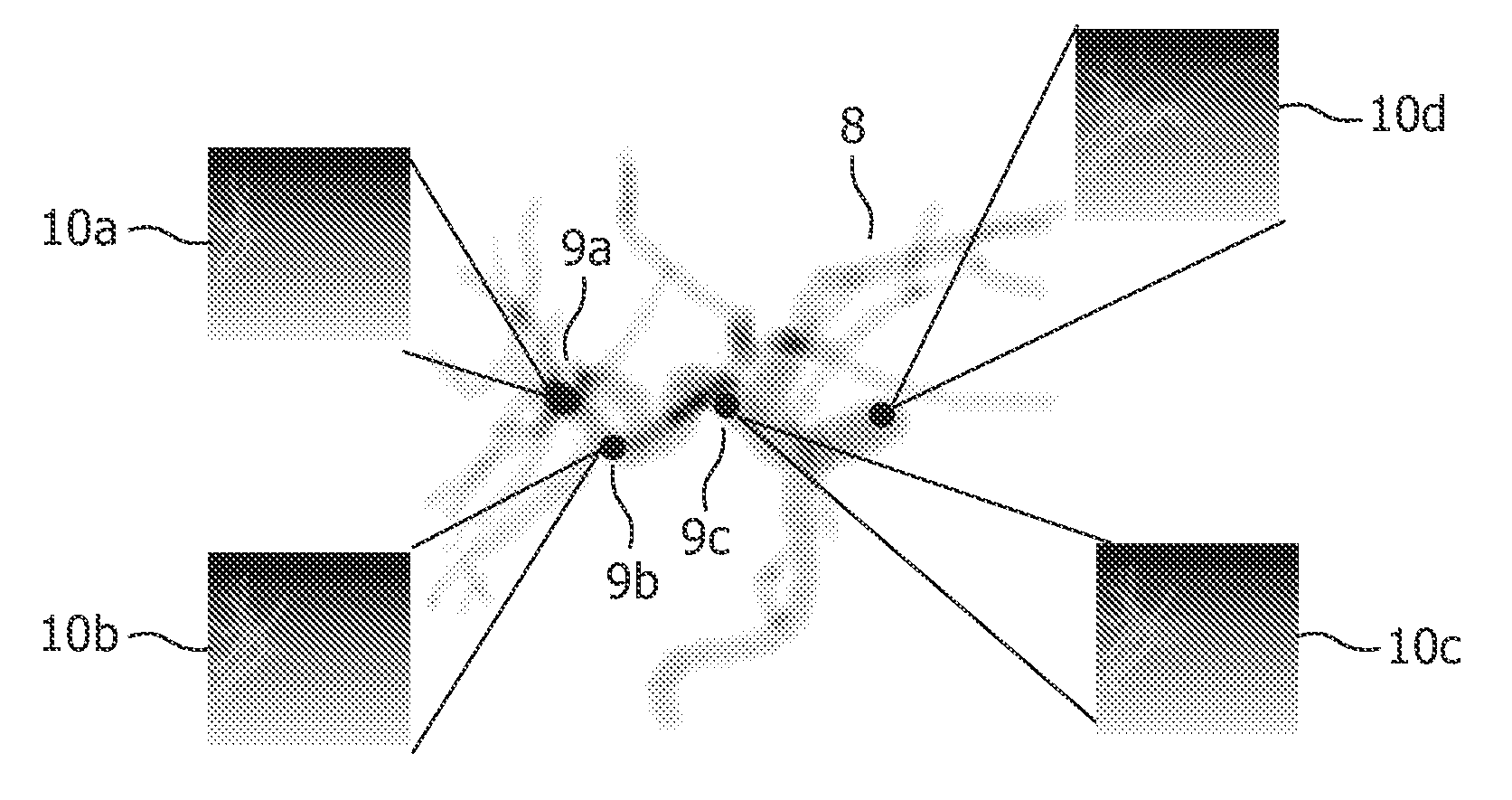
[0095]Similar or relating components in the several figures are provided with the same reference numerals. The view in the figure is schematic and not fully scaled.

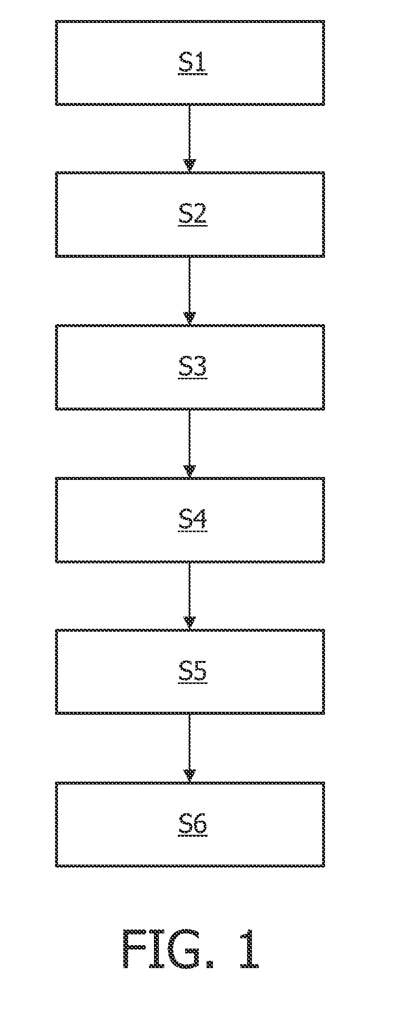
[0096]FIG. 1 shows a possible core method of image processing according to an embodiment of the present invention, wherein this method comprises the following steps: Gathering a tube model of a tube tree with at least one tube from the tube data set S1, selecting a virtual injection point of a medium S2, defining a direction with respect to the virtual injection point S3, simulating a dynamic flow of the medium starting at the user-defined virtual injection point S4, wherein the simulation is generated on basis of flow characteristics, wherein the medium flows through the at least one tube of the tube model using the simulation to generate at least two dynamic images S5 and displaying the dynamic images S6. Thereby the flow simulation might be a three dimensional visualisation.

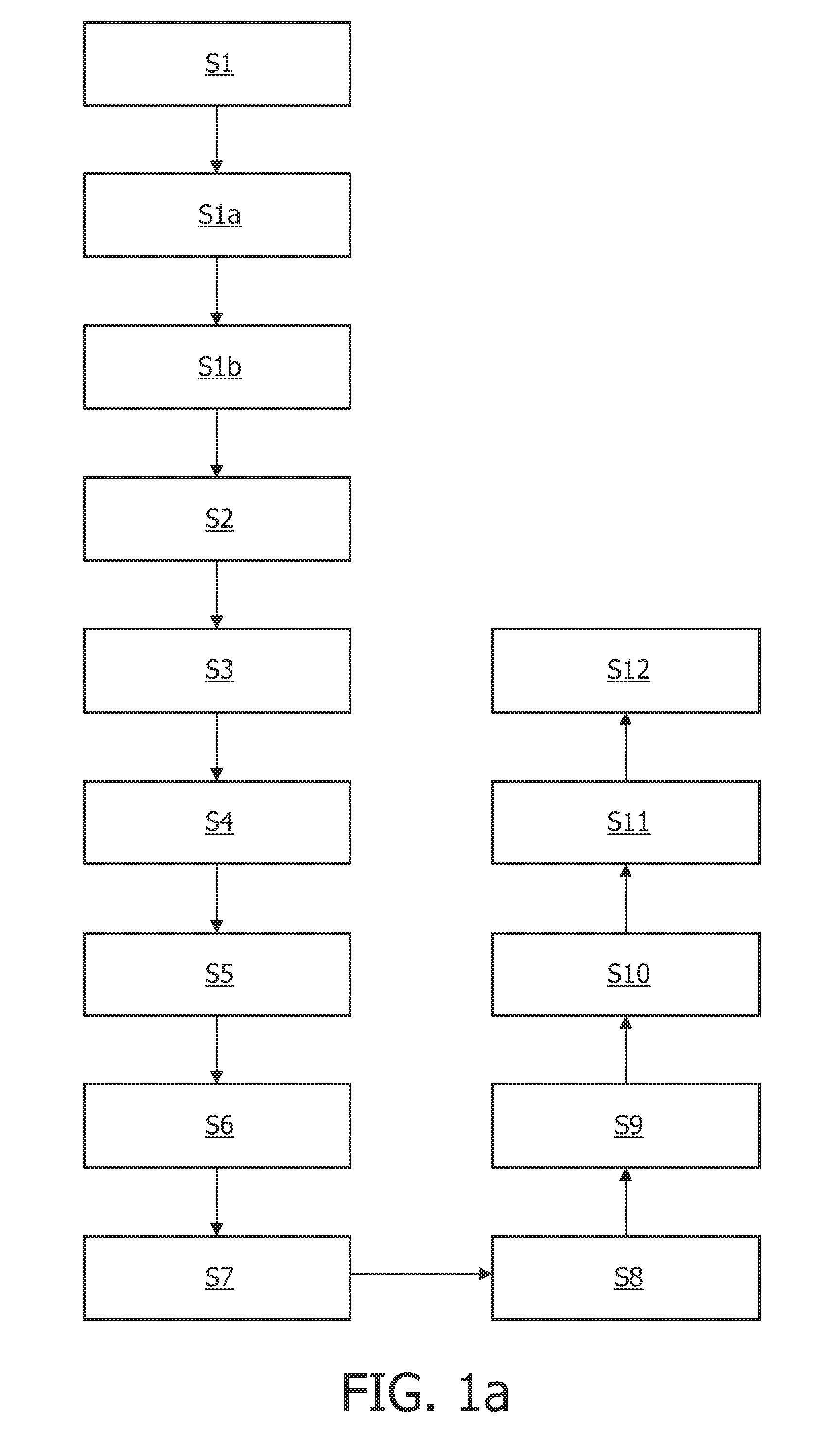
[0097]FIG. 1a describes the step of a method ...


PUM


Abstract

A method of analyzing a tube system in particular by image processing of images of the tube system is provided by the present invention. In order to achieve a simulation of a medium flow through a calculated tube model, the present invention gathers a tube model from a specific tube data set. By defining the necessary parameters of a virtual injection of the medium by the user, the medium flows through the model. Using this displayed simulation for generating at least two images leads to an artificial image sequence that might support a person, which wants to examine a real structure, that corresponds to the calculated model. This might be seen in.

Description

FIELD OF THE INVENTION[0001]The present invention relates to the field of analyzing a tubular system, more specifically the invention relates to a method for image processing of a tube system, a respective apparatus and software elements.BACKGROUND OF THE INVENTION[0002]In many medical procedures, a catheter or other different kind of devices are inserted into tube systems like the arterial system of a patient, and guided to a target location inside the body. This procedure is generally done under imaging guidance using for example a C-arm type of a fluoroscopic apparatus. Periodically, the operating physician takes an X-ray snapshot to see where the tip of the catheter is located or, in the event of difficult manipulations, these are performed by the physician under continuous fluoroscopic imaging.[0003]C-arm based X-ray imaging is the modality of choice for many vascular interventions. In applications such as neuro vascular or hepatovascular treatment, the treatment is often compl...

Claims


Application Information

Patent Timeline
IPC IPC(8): G06T7/00
CPCG06T17/00G06T7/0012G06T7/0016G06T2207/10116G06T2207/10081G06T2207/30101G06T2207/30104G06T2207/30021G16H50/50
Inventor MOLLUS, SABINEBREDNO, JOERGWEESE, JUERGENBABIC, DRAZENKO
Owner KONINKLJIJKE PHILIPS NV
Learn More