
Cerebral blood flow quantification device, cerebral blood flow quantification method and program

a blood flow and quantification method technology, applied in the field of cerebral blood flow quantification devices, cerebral blood flow quantification methods and programs, can solve the problems of reducing quantification accuracy, serious aftereffects, and disadvantages of being highly invasive, and achieve the effect of accurately quantifying the cerebral blood flow ra

Inactive Publication Date: 2011-01-06
NIHON MEDI PHYSICS CO LTD
View PDF1 Cites 2 Cited by
  • Summary
  • Abstract
  • Description
  • Claims
  • Application Information

AI Technical Summary

Benefits of technology

[0010]A purpose of the invention made in view of the above-mentioned circumstances is to provide a cerebral blood flow rate quantification device that can accurately quantify the cerebral blood flow rate at a relatively early stage after administration of a radiopharmaceutical as well as at a late stage after administration.

Problems solved by technology

Cerebral vascular disorders, typified by cerebral infarction, rank high as causes of death, and sometimes leave serious aftereffects in cases of delayed discovery and delayed treatment.
This method has an advantage of being theoretically simple and easy to calculate, but it has a disadvantage of being highly invasive due to its requirement for continuous arterial blood sampling.
The method is also disadvantageous in that because agent washout from tissue to blood vessels is not considered, quantification accuracy decreases at a late stage after administration of the agent and the data collection time point is limited to a relatively early stage after administration.
The NIMS method has been suggested which estimates an input function using a time activity curve based on dynamic SPECT data of a breast instead of performing continuous arterial blood sampling, but it also is a method based on a 1-compartment model and cannot provide sufficient quantification accuracy at a late stage after administration of the agent.

Method used


Image

  • Cerebral blood flow quantification device, cerebral blood flow quantification method and program
  • Cerebral blood flow quantification device, cerebral blood flow quantification method and program
  • Cerebral blood flow quantification device, cerebral blood flow quantification method and program

Examples


examples

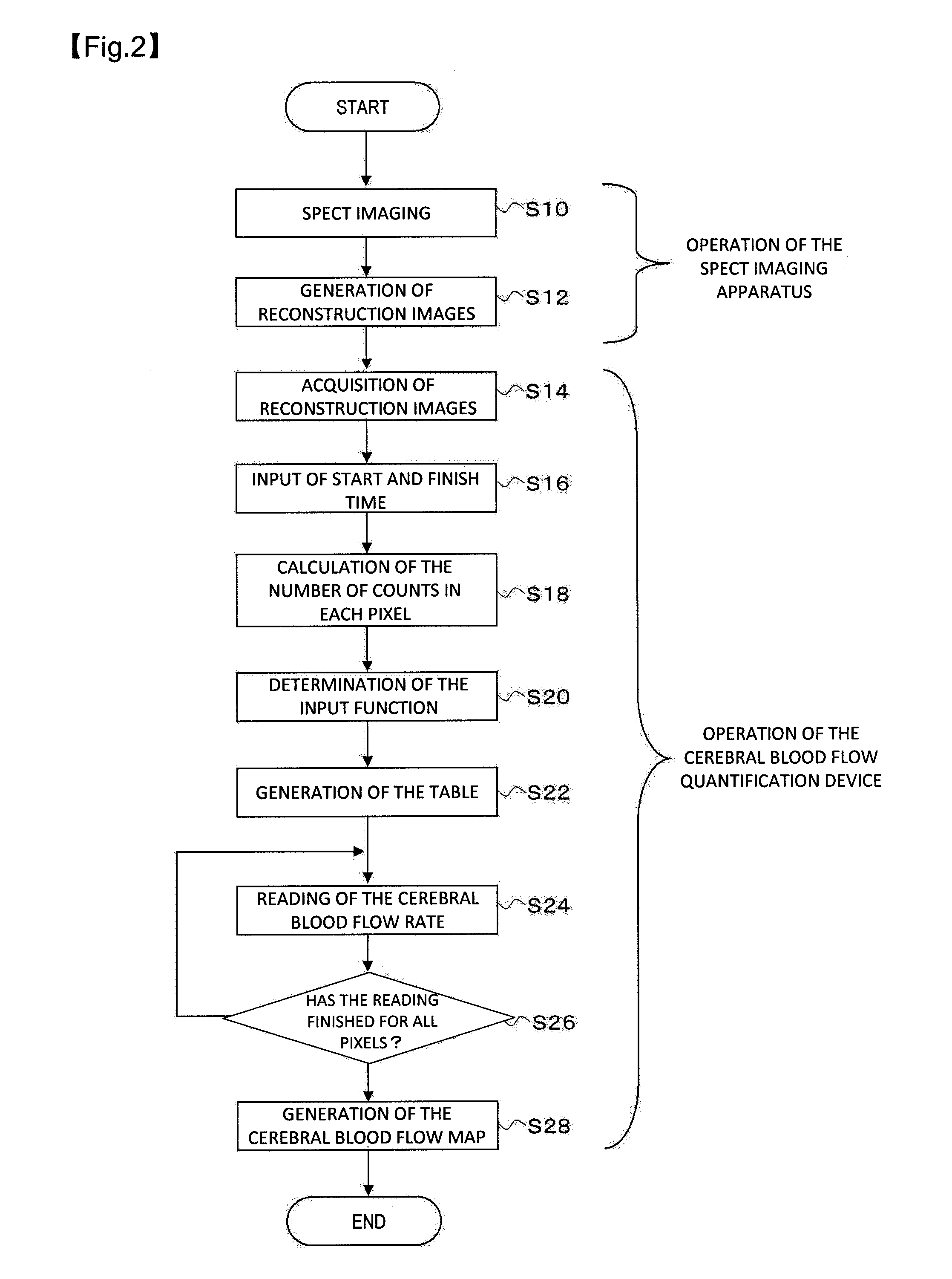
[0061]Working examples and a comparative example will be shown below to describe the invention in further detail, but the invention is not limited to the following. In the working examples, regions of interest were set in reconstruction images, and the cerebral blood flow rate in the set regions of interest was quantified on the images by using reconstruction images imaged in the following time: (Example 1) 0-10 minutes; (Example 2) 10-20 minutes; (Example 3) 0-20 minutes; (Example 4) 15-35 minutes; and (Example 5) 15-25 minutes. As a comparative example, the cerebral blood flow rate in the regions of interest was quantified by a conventional method by using reconstruction images imaged in 15-35 minutes after administration of an agent.

[Collection of SPECT Data]

[0062]A subject was administered with 123I-IMP (200 MBq), and 14 successive scans of dynamic. SPECT data were collected at 2.5 minutes per scan.

[Correction of a Standard Input Function]

[0063]An input function was determined b...

examples 1 to 5

Calculation of the Cerebral Blood Flow Rate in the Working Examples

(Creation of Tables)

[0065]In the working examples according to the invention, the above-described equation (1) was used as the function expressing the concentration of the radiopharmaceutical. In Example 1, the first time t1 was 0 minute, the second time t2 was 10 minutes, and the left side was substituted with 1, in the equation (1); and then fitting was performed according to the Gauss-Newton algorism to calculate the value of k1. This operation was successively performed with the left side substituted with integers ranging from 2 to 1000, and Table 1 showing k1 versus an arbitrary number of counts was created.

[0066]The same operation as described above was performed: in Example 2 with the first time t1 being 10 minutes and the second time t2 being 20 minutes; in Example 3 with the first time t1 being 0 minute and the second time t2 being 20 minutes; in Example 4 with the first time t1 being 15 minutes and the seco...


PUM


Abstract

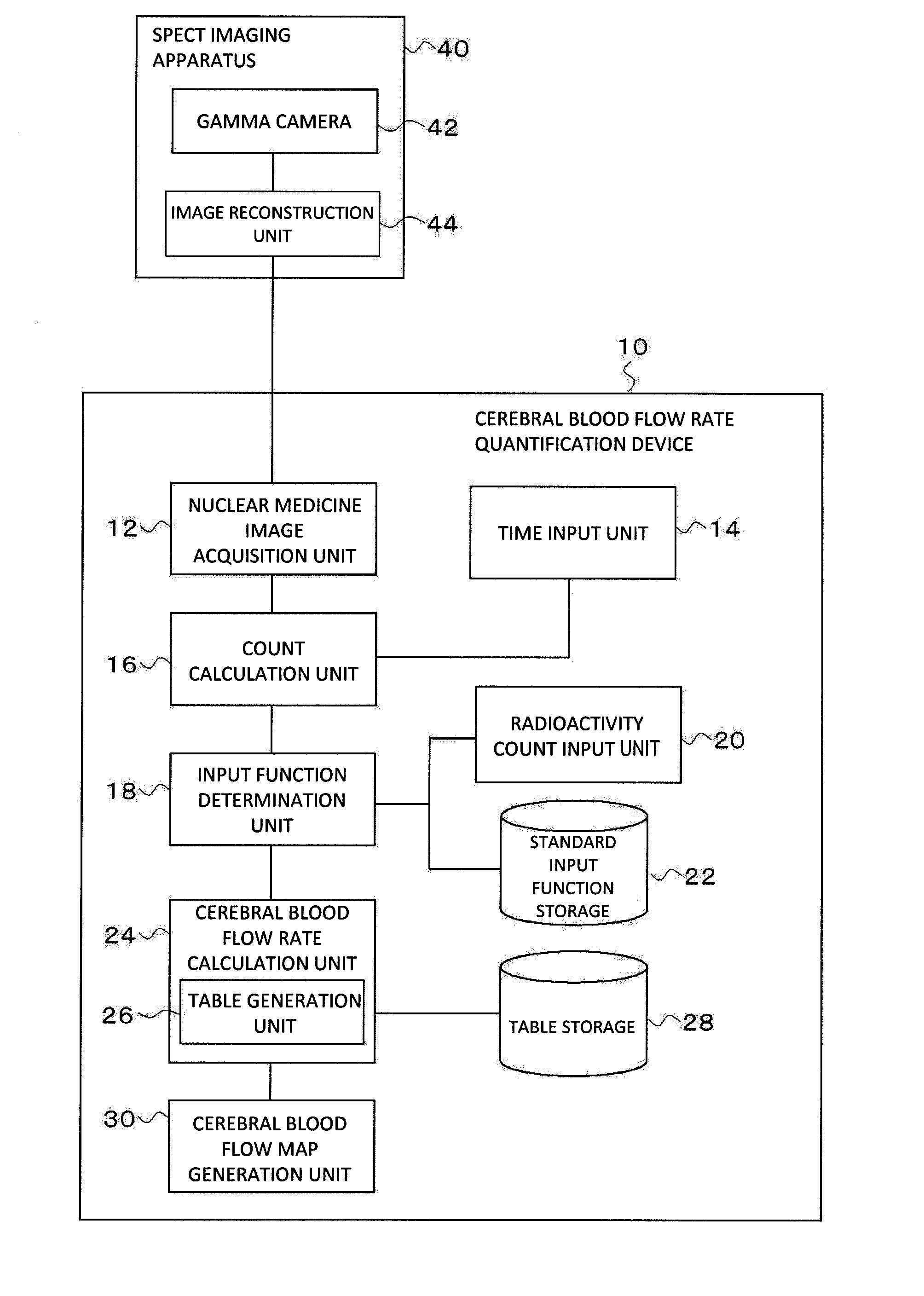
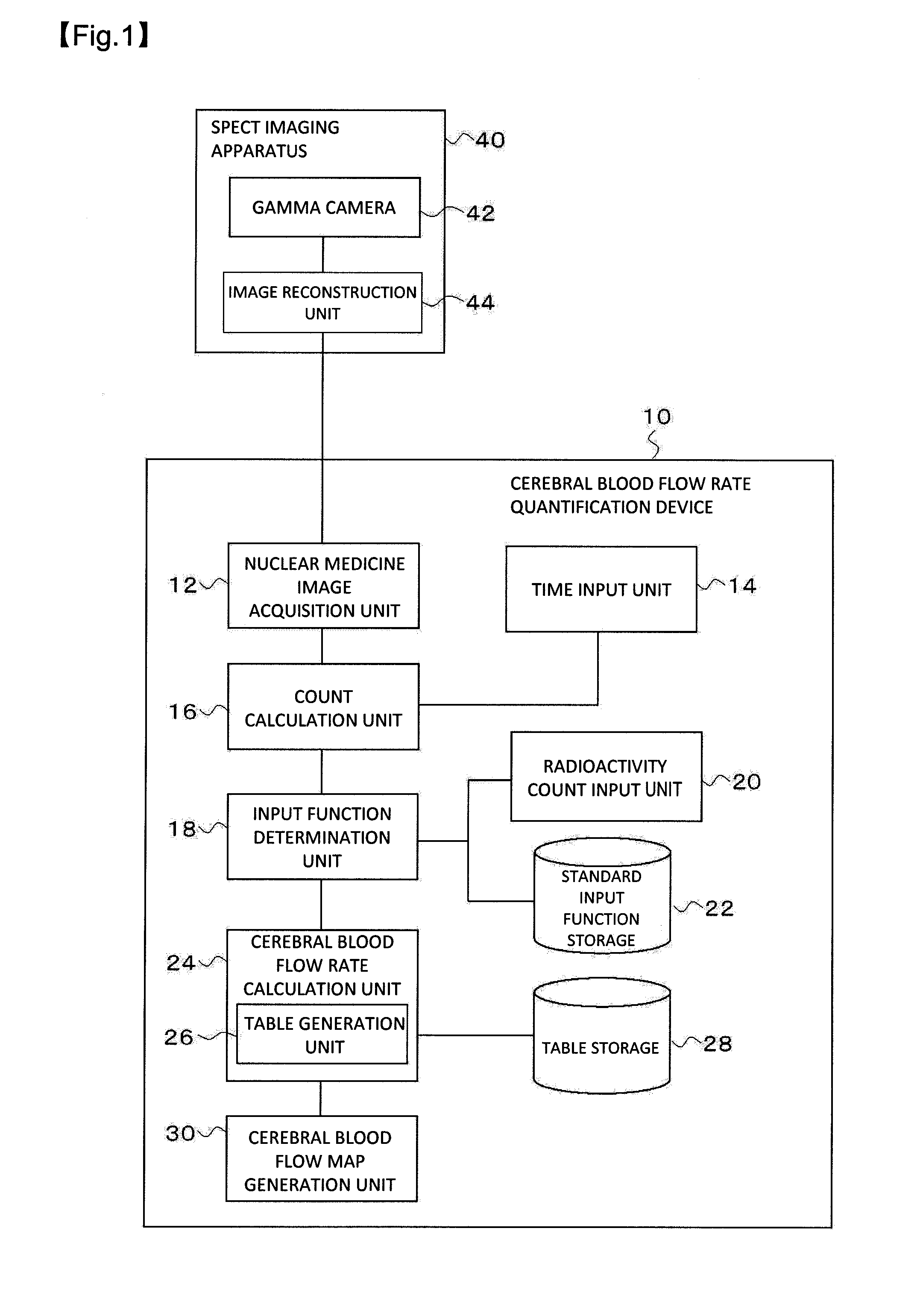
A cerebral blood flow rate quantification device includes: a nuclear medicine image acquisition unit for acquiring a nuclear medicine image of the head of a subject administered with a radiopharmaceutical; a count calculation unit for calculating the number of counts obtained from a unit region; a cerebral blood flow rate calculation unit for calculating the value of a cerebral blood flow rate that makes the value of a function, which expresses the concentration of the radiopharmaceutical in brain tissue; and a cerebral blood flow map generation unit for generating a map showing cerebral blood flow based on the cerebral blood flow rate in each unit region. Consequently, the cerebral blood flow rate can be accurately quantified even at a relatively early stage after administration of a radiopharmaceutical.

Description

RELATED APPLICATIONS[0001]This application claims the benefit of Japanese Patent Application No. 2008-031922 filed on Feb. 13, 2008 in Japan, the contents of which are incorporated herein by reference.TECHNICAL FIELD[0002]The present invention relates to a device and method for quantifying the cerebral blood flow rate.BACKGROUND ART[0003]Cerebral vascular disorders, typified by cerebral infarction, rank high as causes of death, and sometimes leave serious aftereffects in cases of delayed discovery and delayed treatment. Early detection and diagnosis of the severity of cerebral vascular disorders are therefore very important.[0004]As well as MRI and CT, nuclear medicine image diagnosis typified by SPECT or the like is known as a major diagnostic method for cerebral vascular disorders. Nuclear medicine image diagnosis can relatively easily quantify cerebral blood flow at the tissue level, and is therefore widely used for early diagnosis and diagnosis of the severity of cerebral vascul...

Claims


Application Information

Patent Timeline
Patent Type & Authority Applications(United States)
IPC IPC(8): G06T7/00
CPCA61B5/02755G06T7/0012G06T2207/10104A61B6/037G06T2207/30016A61B6/507G06T2207/10108
Inventor ABURANO, TAMIOSHUKE, NORIYUKINISHIKAWA, KAZUHIROTAMAMRUA, NAOYUKI
Owner NIHON MEDI PHYSICS CO LTD
Learn More