Forming Multiple Deviated Wellbores

Inactive Publication Date: 2011-01-13
GEA DELTA TECH
View PDF25 Cites 35 Cited by
  • Summary
  • Abstract
  • Description
  • Claims
  • Application Information

AI Technical Summary

Benefits of technology

[0019]Various embodiments of a multiple deviated wellbore system according to the present disclosure may include one or more of the following features. For example, the deviated wellbore system may include one or more horizontally-drilled wellbores drilled through one or more formations located above a targeted productive formation and a number of sharp-dipping wellbores into or through a productive formation. As used herein, “formation” may include one or more portions, or the entirety, of a body, or strata, of rock. The result may allow for easier, more efficient, and economical penetration into the target productive formation, greater efficiency in drilling the target productive formation and easier communication of fractures through and, in some cases, rubbilization of the formation. The deviated wellbore system m

Problems solved by technology

However, a number of productive formations that may be drilled vertically using the air circulation process may not be easily and/or efficiently drilled horizontally using the air circulation process.
The geologic characteristics of these formations and the altered flow dynamics of circulation mediums involved in drilling horizontal wellbores may make horizontal drilling through these formations difficult and expensive.
Horizontal wellbores through these formations may thus be difficult to drill even using the less efficient fluid “drilling mud” method.
Various natural gas producing regions of the United States, for example, may contain productive formations with great productive potential but which are composed of a highly organic shale rock that may be unsuitable for horizontal drilling using compressed air circulation drilling processes.
In some cases, howe

Method used


Image

  • Forming Multiple Deviated Wellbores
  • Forming Multiple Deviated Wellbores
  • Forming Multiple Deviated Wellbores

Examples


Embodiment Construction

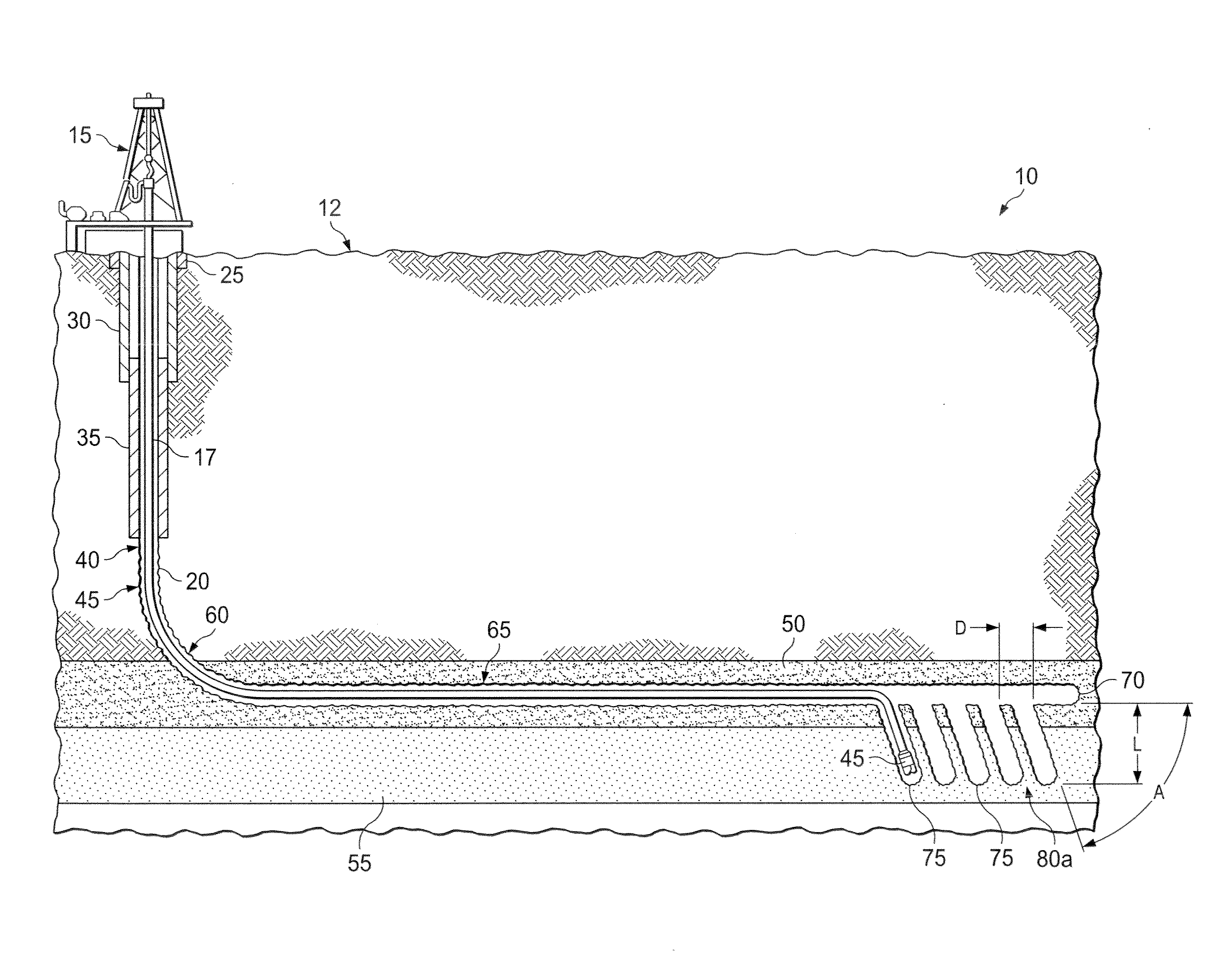
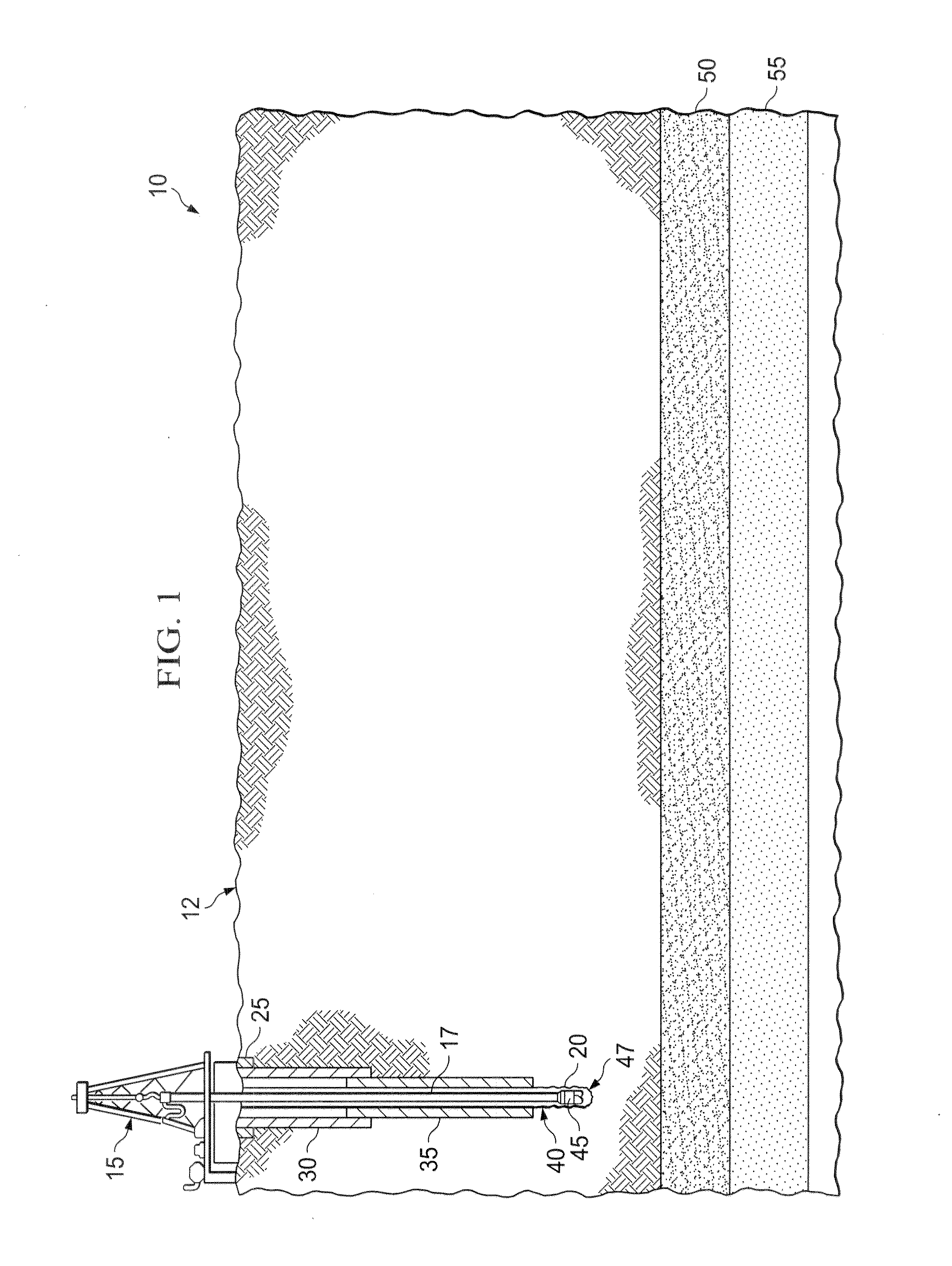
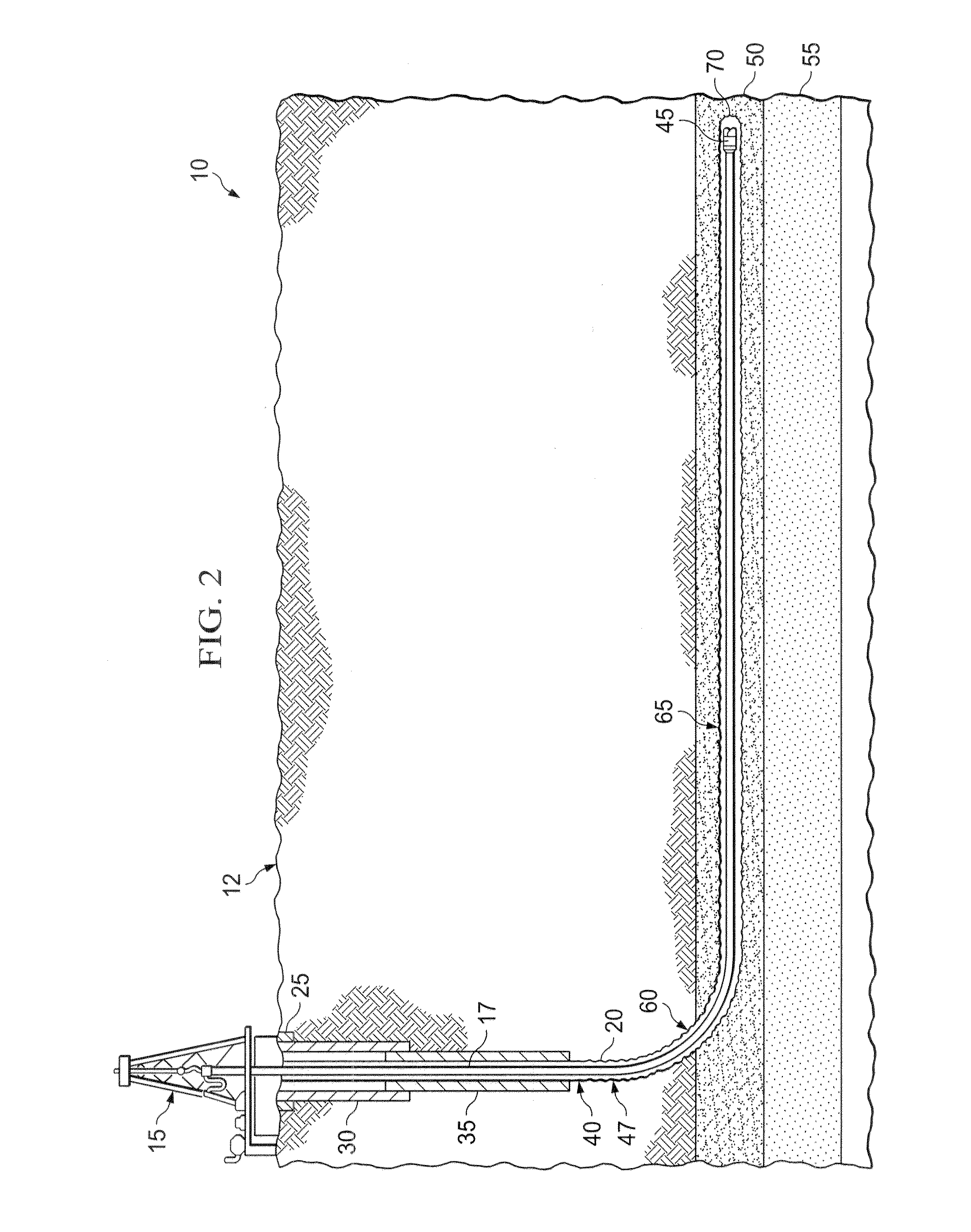
[0030]In some embodiments, a deviated wellbore system according to the present disclosure includes an articulated wellbore drilled from the surface to a target geological formation located above the target productive formation. The articulated wellbore may include a substantially vertical portion, a radiused portion, and a substantially horizontal portion landing in the target geological formation to be drilled horizontally. In some embodiments, the target geological formation is located adjacent a production formation containing one or more hydrocarbons, such as oil or gas. In some embodiments, the production formation may be a formation containing natural gas such as a shale formation, siltstone, sandstone matrix or limestone matrix. The deviated wellbore system may also include one or more deviated wellbores, or completion paths (e.g., production, fracture, stimulation paths), drilled from the substantially horizontal portion of the wellbore into the productive formation. Complet...


PUM


Abstract

A system includes a primary wellbore and a plurality of secondary wellbores. The primary wellbore includes a substantially vertical portion extending from a terranean surface to a predetermined location above a first target subterranean formation; a curved portion coupled to the substantially vertical portion and extending through the first target subterranean formation above a second target subterranean formation containing at least one of oil or gas; and a substantially horizontal portion coupled to the curved portion and extending through the first target subterranean formation and adjacent the second target subterranean formation. The plurality of secondary wellbores are coupled to the primary wellbore and extend angularly downward into the second target subterranean formation.

Description

TECHNICAL BACKGROUND[0001]This disclosure relates to systems and methods for forming wellbores within a subterranean formation and, more particularly, to systems and methods for forming wellbores within one or more subterranean formations utilizing one or more deviated wellbore portions extending from an adjacent geological formation to a hydrocarbon bearing formation.BACKGROUND[0002]Over the last century, oil and gas has been produced from hydrocarbon-bearing geologic strata (“productive formation”) within the Earth's crust by drilling vertical wellbores, which penetrate these potentially productive layers. In most cases, the productive formations are horizontally-planed layers of solid sedimentary rock generally found at depths from approximately 2,000 feet to 20,000 feet below the surface. These productive formations usually range from 10 to 200 feet in thickness. Thus, it may be typical for a vertically-drilled oil or gas well to have less than one percent of its total wellbore ...

Claims


Application Information

Patent Timeline
IPC IPC(8): E21B43/00E03B3/11
CPCE21B43/305
Inventor POOLE, JAMES MICHAEL
Owner GEA DELTA TECH
Why Eureka
Try Eureka