Application of conformal sub boundary layer vortex generators to a foil or aero/ hydrodynamic surface

a sub-border layer and generator technology, applied in the field of aero/hydrodynamic surfaces, can solve the problems of adverse effects of the resultant flow, achieve the effects of reducing the onset of the tip vortex rollup, and improving the lift and drag ratio

Inactive Publication Date: 2011-01-13
IRELAND PETER
View PDF70 Cites 75 Cited by
  • Summary
  • Abstract
  • Description
  • Claims
  • Application Information

AI Technical Summary

Benefits of technology

[0038]At a trailing edge of a foil or surface, it is advantageous to apply a series of conformal sub boundary layer vortex generators, with the apex facing forward toward the flow, to develop a set of counter rotating vortices to interact with and disrupt the Von Karman Street sheet into filaments, thereby delaying the onset of tip vortex rollup. Said trailing edge mechanisms additionally advantageously develop a transverse vortex in the wake of the base of the generator, which acts as a lift enhancing tab, advantageously improving lift and drag ratios in specific operational cases. Such an application advantages the lift distribution on a span, by unloading the tip of the span.
[0039]It is further advantageous to provide vortex generation with a mechanism that adds low mass to a system.
[0040]Damage tolerance by material and by design is advantageous for a vortex generating and flow modification system.

Problems solved by technology

It should be noted that in cases where a squat triangular form is produced, and the hypotenuse to adjacent angle is large, in excess of 60 degrees, then the resultant flow may actually be adversely affected such as to increase drag compared to a continuous transverse aft facing step.

Method used


Image

  • Application of conformal sub boundary layer vortex generators to a foil or aero/ hydrodynamic surface
  • Application of conformal sub boundary layer vortex generators to a foil or aero/ hydrodynamic surface
  • Application of conformal sub boundary layer vortex generators to a foil or aero/ hydrodynamic surface

Examples


Embodiment Construction

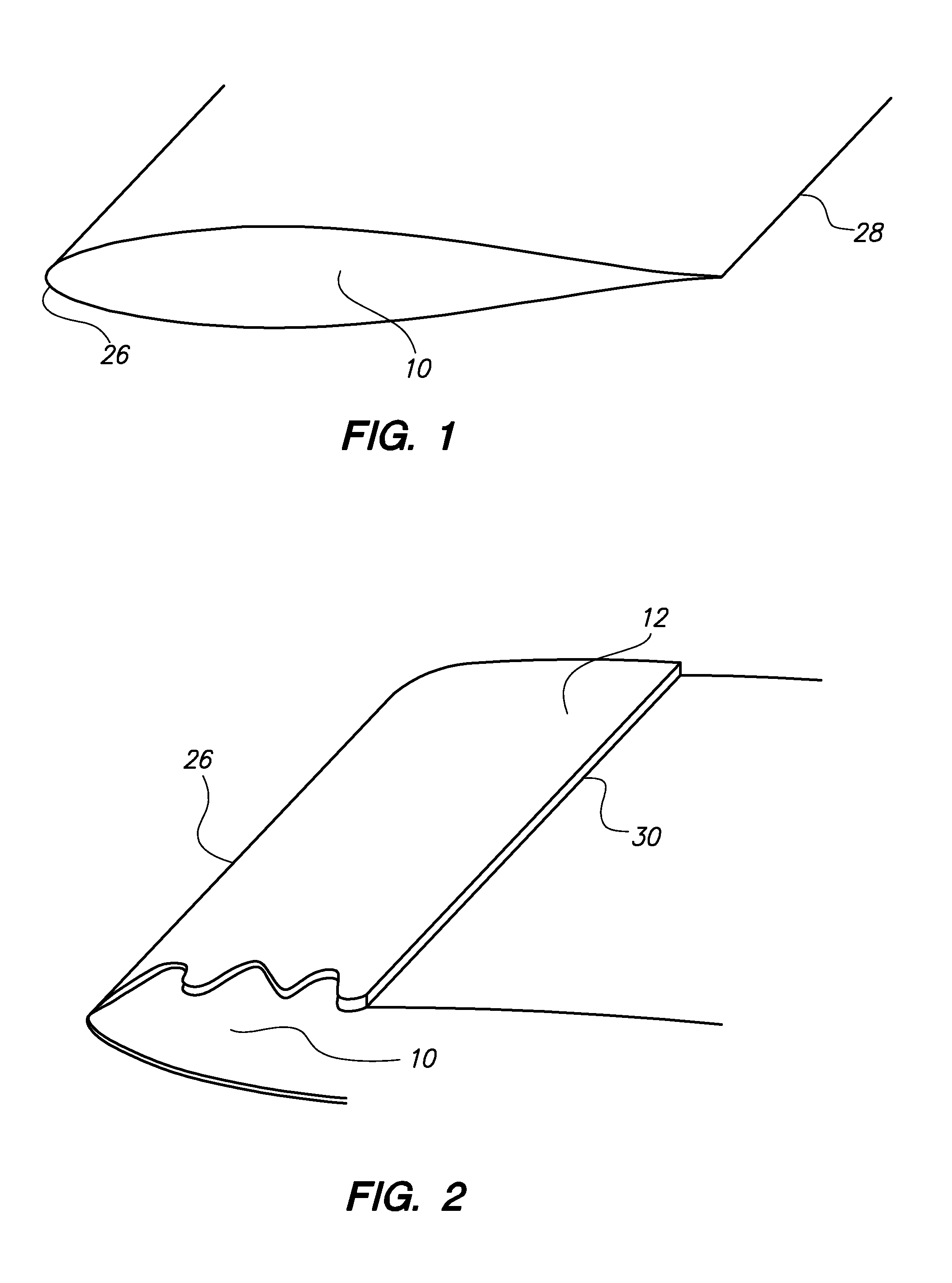
[0055]FIG. 1 is a top perspective view of a generic foil. This drawing shows the foil leading edge 26, foil or aero / hydrodynamic surface 10, and foil trailing edge 28.

[0056]FIG. 2 is a top perspective view of a foil with a current art erosion protection layer 12 or tape applied, to a foil or aero / hydrodynamic surface 10. It can be seen that the process of placing a tape around a foil leading edge 26 results in two aft facing edge 30 elements being produced, on the upper and lower faces of the foil or aero / hydrodynamic surface 10.

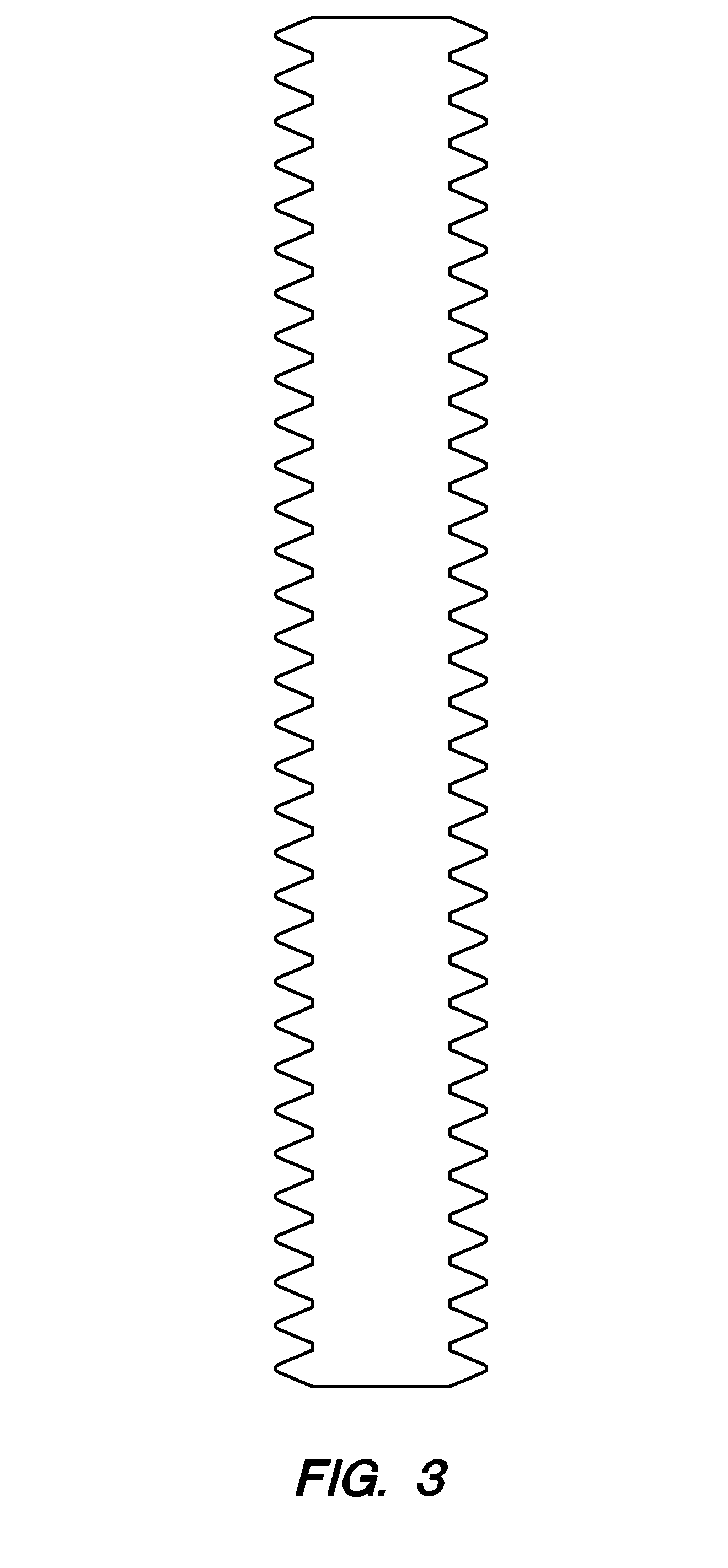
[0057]FIG. 3 is a top plan view of an elastomeric erosion protection layer 12 tape or application medium 14 tape element incorporating sub boundary vortex generators.

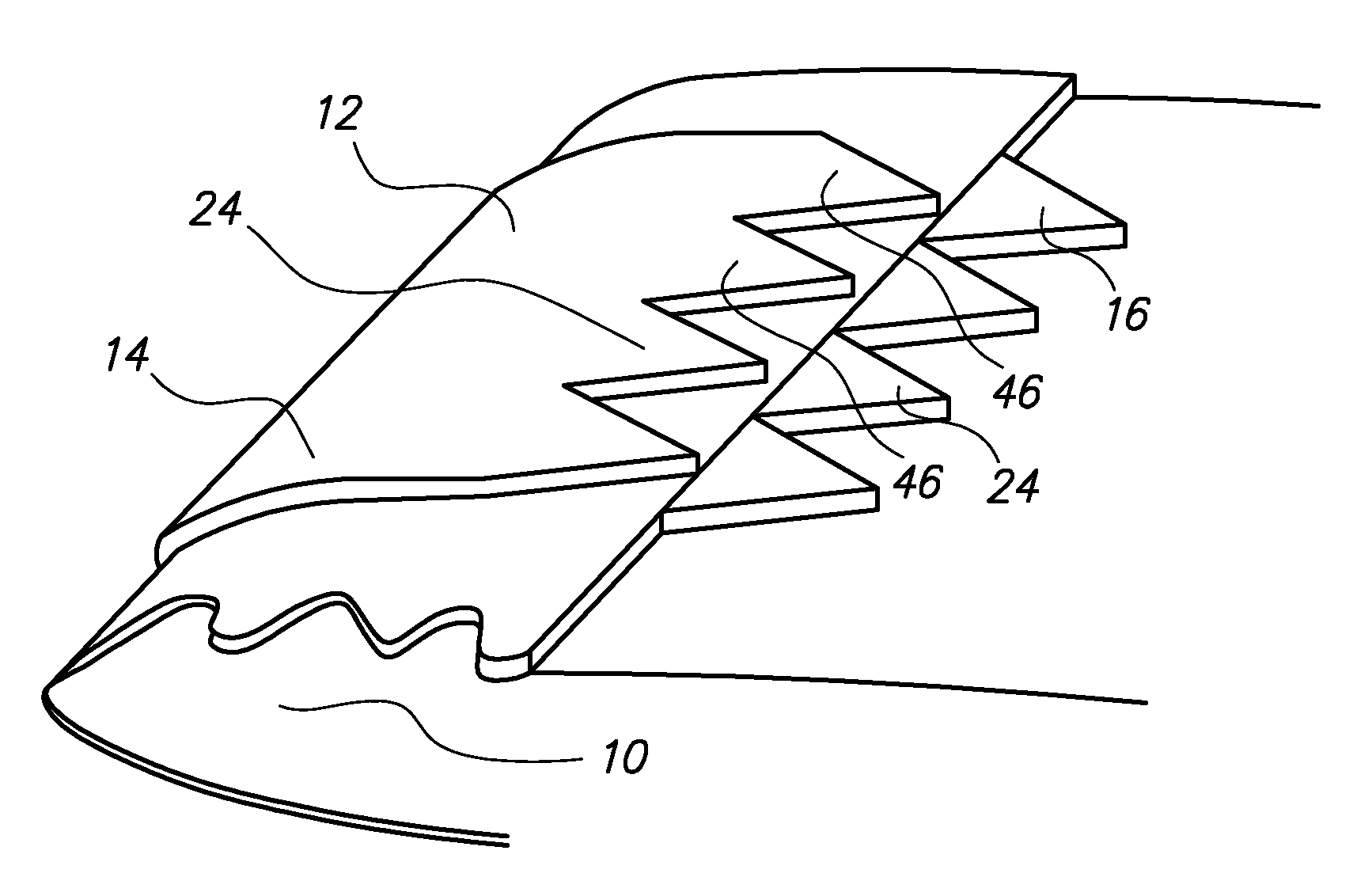
[0058]FIG. 4 is a top perspective view of a current art erosion protection tape with v form sub boundary layer vortex generators 16 applied at the aft facing edge 30. sub boundary layer vortex generators 24 are applied abutted in this case to the aft facing step or lapjoint 48 of the structure, ...


PUM


Abstract

A method of improving aerodynamic performance of foils by the application of conformal, low drag vortex generators. A film of erosion protection material or other conformal material is placed on the foil to provide a medium for the incorporation of planform edge vortex generators. The form edge is shaped to achieve submerged vortex generating shapes of chevron or ogival planforms, extending primarily chordwise on the foil surface. The vortex generators promote improved boundary layer dynamics by mixing free stream flow into the boundary layer while minimising separation and fluid losses. At the trailing edge, the shape formed with the chevrons applied apex forward, acts as a vented gurney tab series and additionally as disruptors to the Von Karman Street wake, delaying sheet rollup into the tip vortice.

Description

RELATED APPLICATIONS[0001]The present application is a continuation-in-part application of U.S. provisional patent application, Ser. No. 61224481, filed Oct. 7, 2009, for ELASTOMERIC VORTEX GENERATORS, by Peter S. Ireland, included by reference herein and for which benefit of the priority date is hereby claimed.[0002]Elastomeric Vortex Generator Provisional patent, Ireland P S, of 10 Jul. 2009. (EFS ID 5676629 Application Number 61224481 Confirmation Number 2708 Title Elastomeric Vortex Generator(s) First Named Inventor Peter Stephen Ireland)FIELD OF THE INVENTION[0003]The present invention relates to the addition of low drag fully submerged conformal vortex generators to a surface in relative motion to a Newtonian fluid and, more particularly, to aeronautical and marine surfaces, blades, rotors, and appendages having a boundary layer with fluid flow across such surface.BACKGROUND OF THE INVENTION[0004]Performance of a foil or surface in a flow of fluid such as air or water is criti...

Claims


Application Information

Patent Timeline
Patent Type & Authority Applications(United States)
IPC IPC(8): B64C21/10
CPCB64C23/06B64C23/065Y02T50/164Y02T50/12Y02T50/162B64C2003/147Y02T50/10
Inventor IRELAND, PETER
Owner IRELAND PETER
Why Eureka
Try Eureka