Device and method for measuring parts

a technology for parts and devices, applied in the direction of distance measurement, instruments, and reradiation, etc., can solve the problems of mode hop, apd can actually saturate, and problems such as problems such as problems such as problems such as problems such as apd saturation

Active Publication Date: 2011-01-13
NORDSON CORP
View PDF13 Cites 2 Cited by
  • Summary
  • Abstract
  • Description
  • Claims
  • Application Information

AI Technical Summary

Benefits of technology

[0019]A method of measuring moving material, includes the steps of providing a processor and operating software associated therewith; providing a source for emitting at least two polarized light beams in a manner wherein the beams cross thereby creating an interference region and generate a set of fringes; operably disposing a sensor aligned relative to the interference region wherein the fringes have a predetermined orientation to the directional move

Problems solved by technology

While the above system works well on many surfaces, problems can arise when the surface is smooth and shiny.
In extreme cases, the APD can actually saturate due to too much light.
Another effect of too mu

Method used


Image

  • Device and method for measuring parts
  • Device and method for measuring parts
  • Device and method for measuring parts

Examples


Embodiment Construction

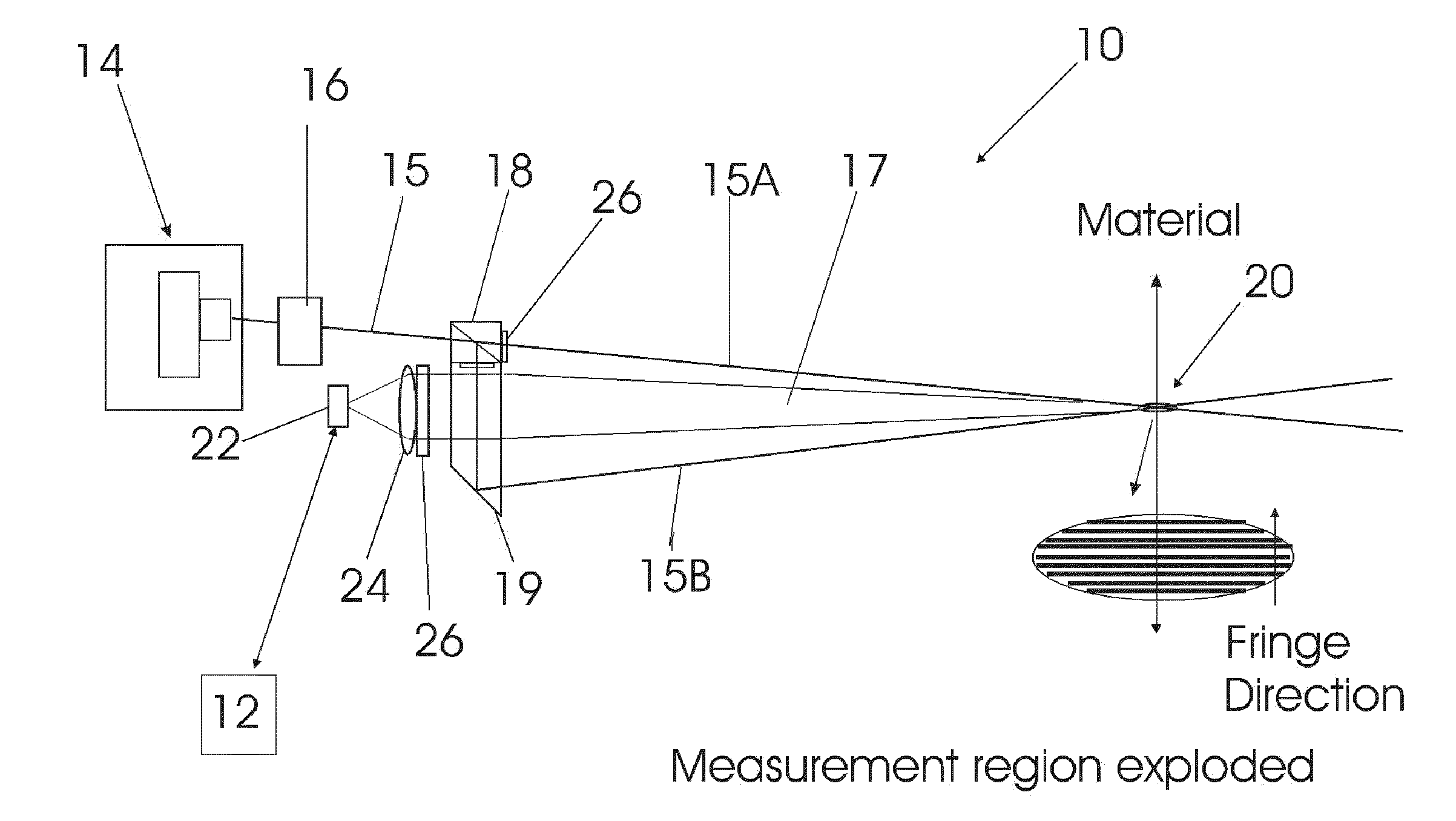
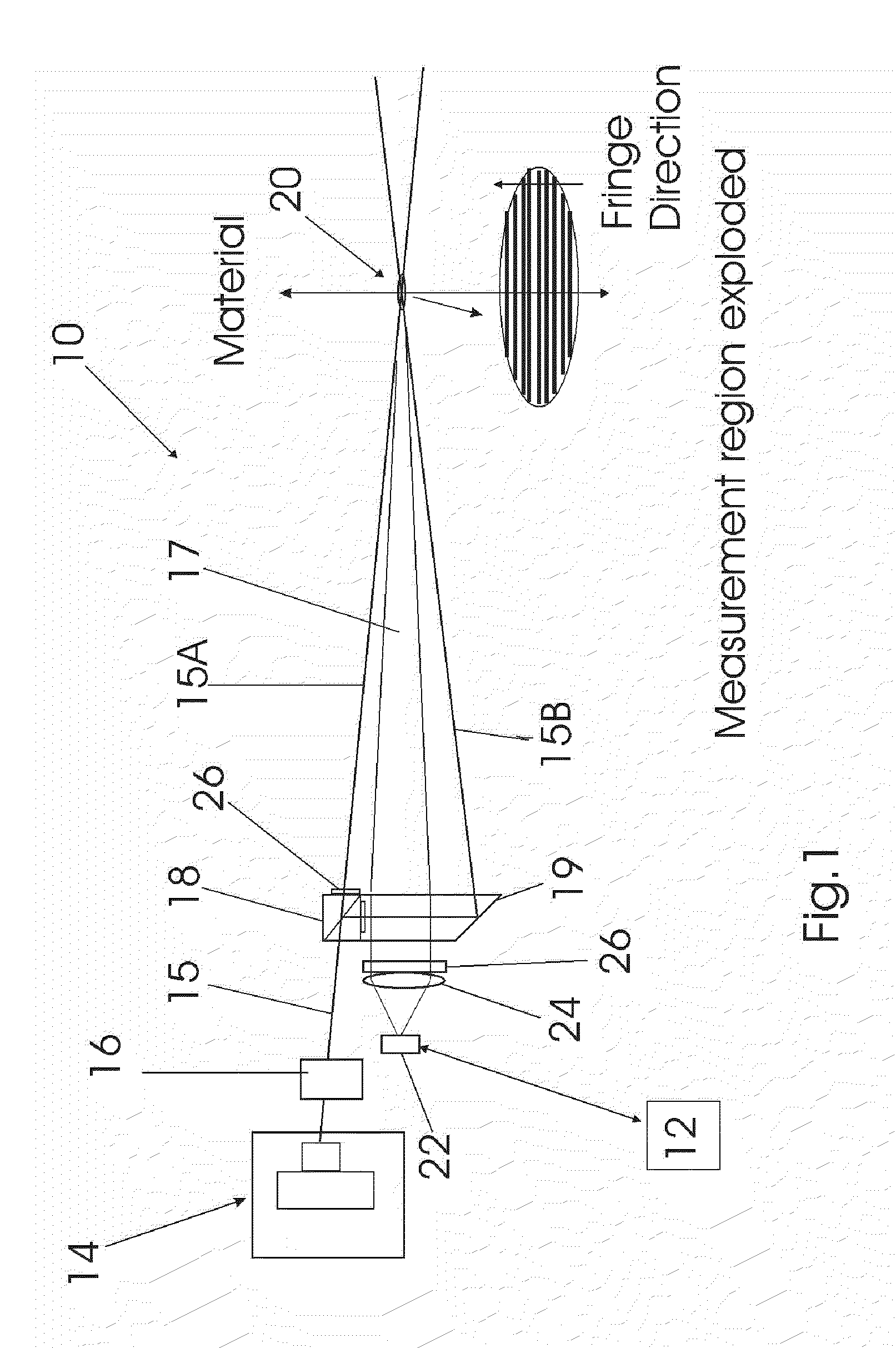
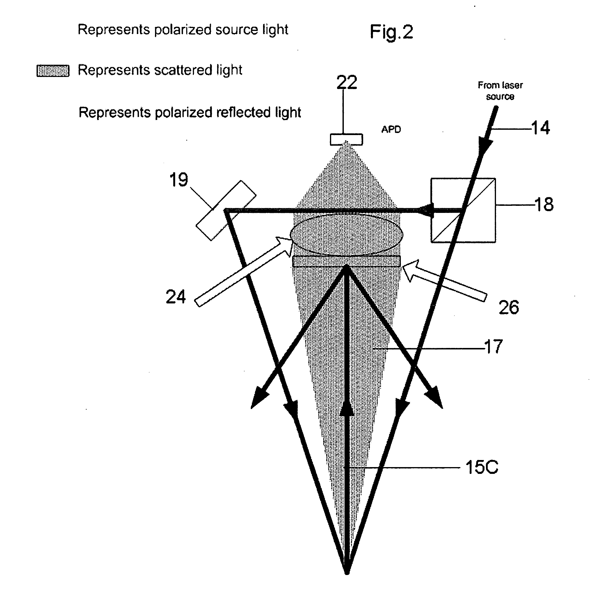
[0023]Referring now to the drawings, the device for measuring moving material of the instant invention is generally designated by the numeral 10. The device 10 can include a processor unit 12 having operating software, hardware and display readout, and operative key board associated therewith. A laser diode 14 can be employed for emitting a light beam 15 which can preferably be passed through an acusto-optical modulator 16 acousto-optic modulator (AOM), also called a Bragg cell, which uses the acousto-optic effect to diffract and shift the frequency of light using sound waves (usually at radio-frequency). The light beam 15 can then be passed through an optical beam splitter 18 to provide two light beams 15A, 15B having the same polarity. The light beams 15A and 15B exit the beam splitter 18 in a non parallel manner wherein the light beams 15A and 15B cross thereby creating an interference region 20 and generating a set of fringes. This can also be referred to as the measurement regi...


PUM


Abstract

A device and method for measuring moving material includes a processor and operating software associated therewith; a light source for emitting at least two polarized light beams in a manner wherein the beams cross thereby creating an interference region and generate a set of fringes; a sensor aligned relative to the interference region wherein the fringes have a predetermined orientation to the directional movement of the material and wherein the sensor is operably equipped to receive scattered light emanating from the interference region and provide a time varying signal to the processor such that the processor can manipulate and convert the signal to speed and distance and a polarizing filter operably associating a polarizing filter with one of the sensor and the emitting means in a manner to substantially preclude reflected polarized light from the interference region back to one of the sensor and the emitting source.

Description

FIELD OF INVENTION [0001]The present invention relates to improvements in devices and methods for measuring parts. More particularly, the invention relates to improvements in measuring moving parts to compensate for reflected and scattered light in the use of laser optics.BACKGROUND OF THE INVENTION [0002]There exist many Laser Doppler Velocimetry devices (LDV) (also known as laser Doppler anemometry, or LDA) to measure the speed and length of moving parts. These devices employ a technique for measuring the direction and speed of material that is processed.[0003]The LDV crosses two beams of collimated, monochromatic, and coherent laser light in the flow of the material being measured. The two beams are usually obtained by splitting a single beam, thus ensuring coherency between the two and have the same polarity and exit the device at an angle. The two beams cross at some standoff distance from the device.[0004]Where the beams cross (intersection) an interference pattern is created....

Claims


Application Information

Patent Timeline
IPC IPC(8): G01P3/36
CPCG01P3/366G01S17/58G01S7/499
Inventor KRABACHER, KENNETH D.JENSON, LESLIE M.
Owner NORDSON CORP
Why Eureka
Try Eureka