Silent chain transmission system

a transmission system and chain technology, applied in the direction of driving chains, valve drives, gearing, etc., can solve the problems of increasing occupying an excessive amount of space, and not being able to maintain a uniform gap between the connecting pins, so as to reduce the space occupied by the sprocket, improve the ability of the chain transmission, and reduce the thickness and weight of the sprocket.

Inactive Publication Date: 2011-01-13
TSUBAKIMOTO CHAIN CO
View PDF1 Cites 9 Cited by
  • Summary
  • Abstract
  • Description
  • Claims
  • Application Information

AI Technical Summary

Benefits of technology

[0022]In an embodiment of the silent chain transmission, the diameter of each flange on at least one of the sprockets can be greater than the diameter of a circle tangent to the tips of the teeth on the sprocket but less than the diameter of an inscribed circle tangent to the connecting pins on a portion of the chain seated on that sprocket. In this case, the flanges will not collide with the connecting pins, and the thickness and weight of the sprocket can be reduced by making the flanges only thick enough that they can function to guide the chain. In this say it is possible to reduce the space occupied by the sprocket and to improve the ability of the chain transmission to follow changes in speed.
[0023]In another embodiment, the diameter of each flange on at least one sprocket can be smaller than the diameter of a circle tangent to the tips of the sprocket teeth but greater than the diameter of a circle tangent to the tips of the teeth on a portion of the chain seated on the sprockets. Here, the weight of the sprocket can be reduced by reducing the diameters of the flanges to the diameter required for the flanges to function as guides. Again, by making the flanges only large enough to function as guides, it becomes possible to reduce the size of the sprocket and to improve the ability of the transmission to follow changes in speed.
[0024]In still another embodiment, where connecting pins extend beyond the widthwise outermost plates of the chain, the diameter of each flange on at a sprocket can be is greater than the diameter of an inscribed circle tangent to the connecting pins on a portion of the chain seated on the sprocket. In this case, the portion of each flange that extends radially outward beyond the inscribed circle can be formed with a recess for receiving the connecting pins without contacting the connecting pins. In this embodiment it is also possible to prevent the flanges from colliding with the connecting pins, to enhance the ability of the flanges to serve as guides, and more reliably prevent the chain from becoming disengaged from the sprocket.
[0025]In still another embodiment, each flange on at least one of the sprockets can have a wave-shaped profile having alternating peaks and troughs shaped so that portions of the sides of the sprocket teeth are exposed through the troughs, and so that portions of the chain disposed between said sprocket teeth are covered by the peaks of the flanges. Adoption of flanges having a wave-shaped profile enables the weight of the sprocket to be reduced without sacrificing the ability of the flanges to serve reliably as guide. By reducing weight, the wave-shaped profiles also improve the ability of the transmission to follow changes in speed.
[0026]The flanges on a sprocket may be connected directly to mounting shaft on which the sprocket is mounted so that the sprocket body is interposed between the flanges. In this case, the flanges can be formed of a light-weight material different from the material of the sprocket body, and the overall weight of the sprocket can be reduced. The use of flanges connected directly to the mounting shaft can also make it possible to reduce occupied space, to improve the ability of the transmission to follow changes of speed, to facilitate mounting of the sprocket body, and other assembly steps.
[0027]Alternatively, the flanges can be mounted on stepped recesses formed on both sides the sprocket body. In this case, the flanges can be rigidly fixed to the sprocket body to enhance their strength as guides. Mounting the flanges on the sprocket body can also facilitate assembly of the sprocket.

Problems solved by technology

In the above-described known silent chain transmission, the guide plates 931 do not contribute to the transmission of power between the sprockets and the chain, and, because they are located at both of the widthwise outermost sides of the chain, the chain becomes wider, and occupies an excessive amount of space.
The lengths of the connecting pins, which extend into or beyond the pin holes of the outermost guide plates of the known silent chain, are at least as great as the widths of the guide rows of the chain, and are subject to considerable bending when the chain is under tension.
Consequently, it is not possible to maintain a uniform gap between the connecting pins and the bushings, and abrasion, vibration and noise occur in the operation of the chain.
The use of guide plates requires a large number of parts and makes assembly of the chain difficult and time-consuming and contributes to the overall weight of the chain.
The use of guide plates and the need for long connecting pins also impair the ability of the chain transmission to respond to changes in speed.

Method used


Image

  • Silent chain transmission system
  • Silent chain transmission system
  • Silent chain transmission system

Examples


first embodiment

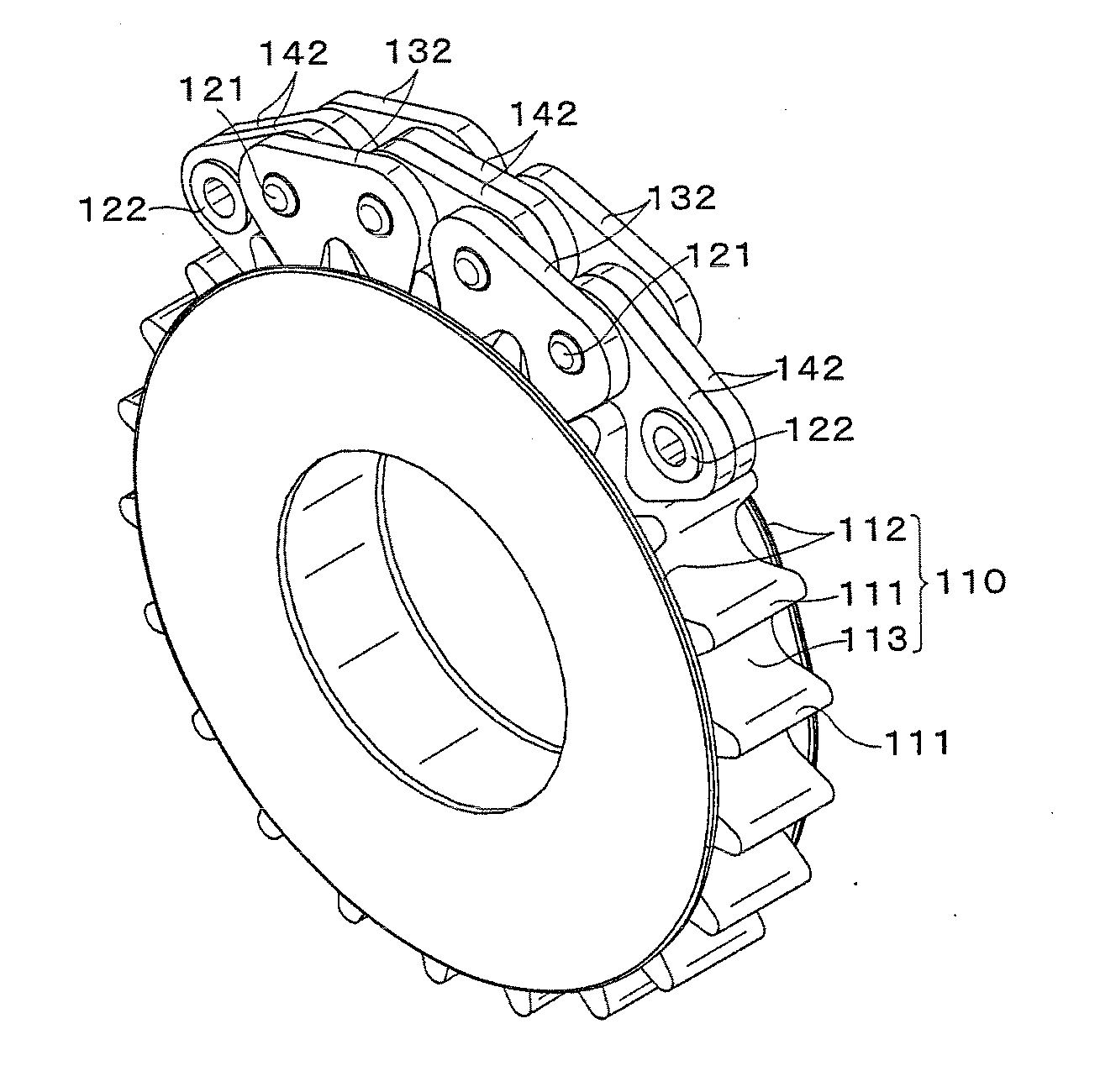
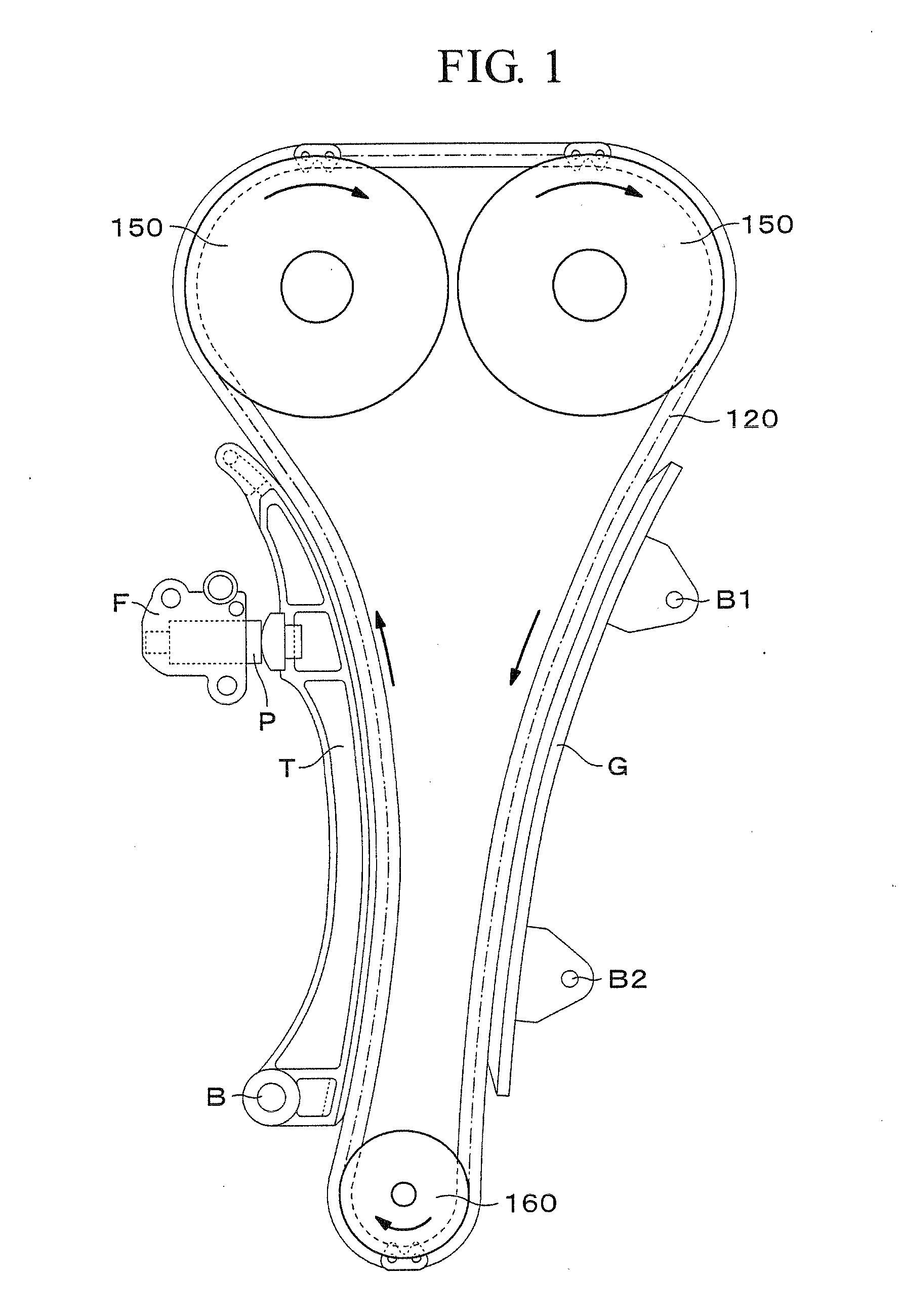
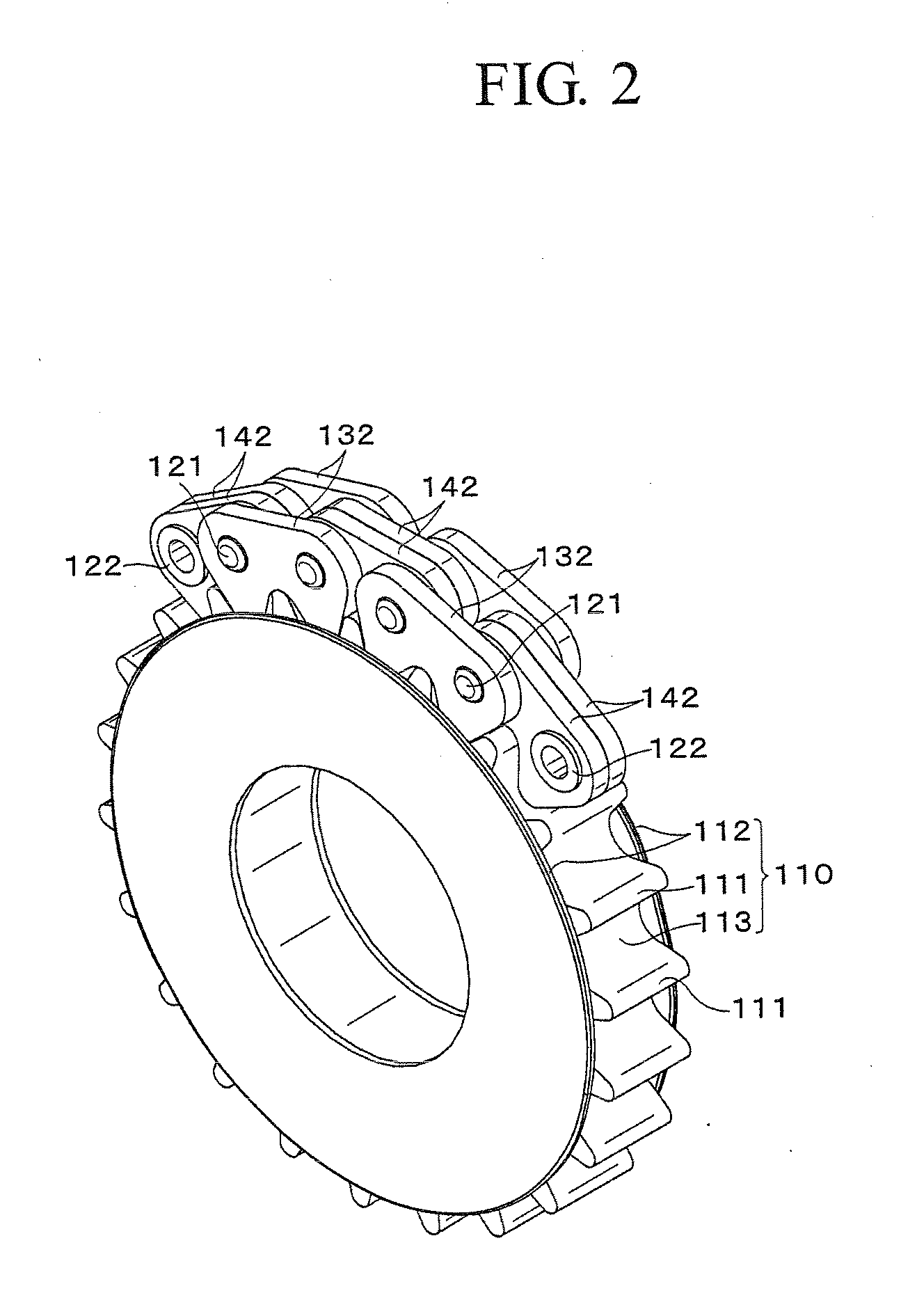
[0053]As shown in FIGS. 2 through 4, the silent chain transmission system of the invention includes a chain 120 that is composed of alternating outer, or first, link rows and inner, or second, link rows, connected by connecting pins 121 and bushings 122, and a sprocket 110. The sprocket can be a driven sprocket 150 (FIG. 1) or a driving sprocket 160 (FIG. 1), and has a sprocket body 113 (FIG. 2) provided with sprocket teeth 111 on it outer peripheral surface thereof and flanges 112 on both sides of the sprocket body and extending outwardly at least beyond the roots of the sprocket teeth 11, for guiding the chain 120.

[0054]As shown in FIGS. 3 and 4, the chain 120 includes outer (first) link rows the first link rows, each composed of a pair of outer link plates 132 each having a pair of front and rear pin holes 133, and inner (second) link rows, each composed of a pair of inner link plates 142, each having a pair of front and rear bushing holes 143.

[0055]Each of the outer link plates ...

third embodiment

[0061]As shown in FIGS. 6 and 7, a silent chain transmission 300 according to the invention comprises a chain 320 whose outer, or first, link rows are flexibly connected to inner, or second, link rows. Each outer link row comprises a pair of outer link plates 332 having pin holes 333, and each inner link row consists of a single link plate 342 having pin holes 343. The outer link plates are connected by connecting pins 321, which are press-fit into holes 333 and extend rotatably through pin holes 343 in the inner link plates. The chain cooperates with a sprocket (not shown but similar to the sprocket in FIG. 2) having a sprocket body provided with sprocket teeth around the outer peripheral surface thereof and flanges on both sides for guiding the chain.

[0062]Except as described above, the structure and operation of the silent chain transmission of the third embodiment are substantially the same as the structure and operation of the first embodiment.

fourth embodiment

[0063]As shown in FIGS. 8 and 9, a sprocket 210 of a silent chain transmission according to the invention transmits power by engagement of its sprocket teeth 211 with the plate teeth 134 and 144 of the outer and inner link plates 132 and 142 of a chain 120.

[0064]Both sides of the sprocket 210 are provided with flanges 212 which extend beyond the roots of sprocket teeth 211 but not beyond their tips. That is, the diameter of each of flanges 212 is smaller than the diameter of an imaginary circle tangent to the tips of the sprocket teeth and centered on the axis of rotation of the sprocket. On the other hand, the diameter of each the flanges is greater than that of an imaginary circle tangent to the tips of the outer plate teeth 134 in a portion of the chain seated on the sprocket. Accordingly, widthwise movement of the outer link plates 132 is restricted to prevent the plate teeth 134 and 144 from disengaging from the sprocket teeth 111 by widthwise movement of the chain.

[0065]Becaus...


PUM


Abstract

In silent chain transmission comprising a chain composed of rows of link plates connected in articulating relationship by connecting pins, at least one sprocket is provided with a pair of flanges that guide the chain by engaging sprocket-engaging teeth on the outermost plates of the chain.

Description

CROSS REFERENCE TO RELATED APPLICATIONS[0001]This application claims priority on the basis of Japanese Patent Application 2009-160752, filed Jul. 7, 2009.The disclosure of Japanese Patent Application 2009-160752 is herein incorporated by reference.FIELD OF THE INVENTION[0002]The invention relates to a silent chain transmission having a chain with toothed link plates and sprockets having peripheral sprocket teeth for engagement by the teeth of the chain to transmit power. The silent chain transmission has utility in various mechanisms, including, for example, an engine timing transmission in which power is transmitted through a timing chain from an engine crankshaft to one or more valve-operating camshafts.BACKGROUND OF THE INVENTION[0003]A known silent chain transmission typically comprises a chain and at least two sprockets. The chain comprises first and second sets of link rows, each link row comprising at least one link plate. The sets of link rows are arranged in alternating, in...

Claims


Application Information

Patent Timeline
Patent Type & Authority Applications(United States)
IPC IPC(8): F16G13/07
CPCF01L1/02F01L1/022F16H7/06F16G13/04F01L1/053
Inventor OGO, TOSHITAKA
Owner TSUBAKIMOTO CHAIN CO
Why Eureka
Try Eureka