Failover Procedure for Server System

a server system and failover technology, applied in the field of failover procedures for server systems, can solve the problems of increasing system capital and operating costs, and achieve the effect of reducing operating overhead and facilitating scaling up the number of routing appliances in us

Active Publication Date: 2011-01-13
UNILOC 2017 LLC
View PDF100 Cites 74 Cited by
  • Summary
  • Abstract
  • Description
  • Claims
  • Application Information

AI Technical Summary

Benefits of technology

[0012]Once the transfer to the stand-by server is executed, all system components and clients serviced by the system should be communicating with the former stand-by server now assuming the active server role, via the routing appliances. Configuration of the routing appliances and the use of the secure tunnels between the servers and routing appliances are important features for ensuring optimum operability of the failover system. Use of the secure tunnels may allow system architecture to extend beyond the subnet (sub-network) level of components computers and devices that have a common, designated IP address routing prefix. Routing appliances beyond the subnet are able to recognize the origin of server status keep-alive signals received via the secure tunnels. After configuration, status messages received via the secure tunnels can be readily recognized by any routing appliance, regardless of network location. When a failure occurs, routing appliances that are distant (in network topology terms) from the primary and secondary servers can quickly reroute traffic to the stand-by server. Also, operational overhead is reduced because packet exchange is not required, and the quantity of routing appliances in use is consequently more easily scaled up.

Problems solved by technology

Multiple redundancies increase the chances that a failover event will not be disruptive, but increase system capital and operating costs.
Therefore when a failure of the primary server occurs, the routing appliances and the primary server detect the failure virtually simultaneously.

Method used


Image

  • Failover Procedure for Server System
  • Failover Procedure for Server System
  • Failover Procedure for Server System

Examples


Embodiment Construction

[0019]The present technology provides for implementing failover in a redundant computer system, using failure monitoring using coordinated switching in response to detection of failure.

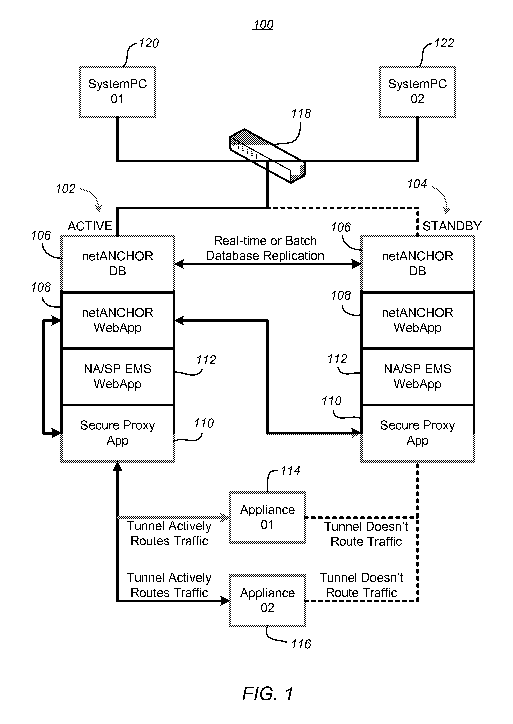
[0020]FIG. 1 shows a single-server deployment system 100, comprising a first server 102 and a second server 104, in an operational state where server 102 is the designated active or primary server and server 102 is the standby or secondary server. Each server 102, 104 may be configured with duplicate components: a database 106, web server component 108, a secure proxy server component 110 operating as proxy for the web server component 108, and an enterprise messaging service (EMS) 112 handling asynchronous messaging between the web server component 108 and the proxy server 110. First server 102 and second server 104 exchange data using a real-time or batch protocol for replication of the database 106, whenever both servers are operational. The database maintained by the primary server 102 is replicat...


PUM


Abstract

A failover procedure for a computer system includes steps for routing traffic from a routing device to a first server, storing in the routing device data representing a fingerprint of the first server, receiving periodically at the routing device a status message from the first server, detecting at the routing device an invalid status message from the first server by absence of the fingerprint in a status message from the first server within a predetermined time period after last receiving a valid status message, and routing the traffic from the routing device to a second server in response to detecting the invalid status message from the first server. A redundant server system implementing the failover procedure may include servers each capable of generating its fingerprint by reading current system configuration data.

Description

[0001]This application claims priority to U.S. Provisional Application No. 61 / 224,372 which was filed Jul. 9, 2009 and which is fully incorporated herein by reference.BACKGROUND[0002]1. Field[0003]The present disclosure relates to methods and systems for managing failover events in computer servers.[0004]2. Description of Related Art[0005]Failover is a backup operational mode in which the functions of a system component (such as a processor, server, network, or database, for example) are assumed by secondary system components when the primary component becomes unavailable through either failure or scheduled down time. Failover protocols and components are often implemented for mission-critical systems that must be constantly available or for busy commercial systems in which down time causes substantial lost income or expenses. A failover procedures transfer tasks to a standby system component so that failover is not discernable, or is only minimally discernable, to the end user. Fai...

Claims


Application Information

Patent Timeline
Patent Type & Authority Applications(United States)
IPC IPC(8): G06F11/20G06F21/00G06F12/14G06F15/173H04L45/28
CPCG06F11/2025G06F11/2038H04L45/28H04L43/0817H04L45/00G06F11/2041
Inventor ETCHEGOYEN, CRAIG STEPHEN
Owner UNILOC 2017 LLC
Why Eureka
Try Eureka