Drain Cartridge Having Removable Valved System

a valve system and cartridge technology, applied in the field of drains, can solve the problems of increasing the cost of waterless urinals, and consuming large amounts of water, and achieving the effect of eliminating the need for flushing water

Active Publication Date: 2011-01-20
GREEN DRAIN
View PDF11 Cites 15 Cited by
  • Summary
  • Abstract
  • Description
  • Claims
  • Application Information

AI Technical Summary

Benefits of technology

[0012]The inventive subject matter provides apparatus, systems and methods in which a cartridge is presented that is sized and dimensioned to be received with a drain. As used herein, the term “drain” means a fluid outlet such as that found in urinals, sinks, tubs, floor drains, or other drains through which fluid can flow. The cartridge can advantageously replace other waterless urinal cartridges including, for example, those having oil or other low-density sealants. The cartridge can include one or more valves that advantageously eliminate the need for flushing water, while avoiding the problems associated with cartridges having low-density sealants. Advantageously, and in contrast to current waterless urinal cartridges having a low-density sealant, the cartridge can be used in urinals and other drains that utilize water to flush the drain, or chemicals to clean the drain housing and cartridge, without degradation of the valves or odor seal.

Problems solved by technology

Because of the need for frequent flushing, large amounts of water are often consumed, which can be problematic especially in areas with limited or no access to water.
The low-density sealant in these cartridges remains open to the atmosphere, which can be problematic as the sealant is depleted, and odors begin to permeate through the seal.
In addition, these cartridges typically require periodic replacement, which can add significantly to the waterless urinals' cost, especially in high traffic areas such as airports and stadiums.
Furthermore, the used cartridges are often hazardous and require properly disposal.
However, such valved systems typically retain a small amount of fluid in the valves after each use, which can cause odors to emanate from the valves.
In addition, the valves are generally prone to freezing in cold regions, and sticking.
In addition, the systems utilize only a single valve, which can be problematic if the valve is stuck open due to sticking or freezing, debris, or otherwise.

Method used


Image

  • Drain Cartridge Having Removable Valved System
  • Drain Cartridge Having Removable Valved System
  • Drain Cartridge Having Removable Valved System

Examples


Embodiment Construction

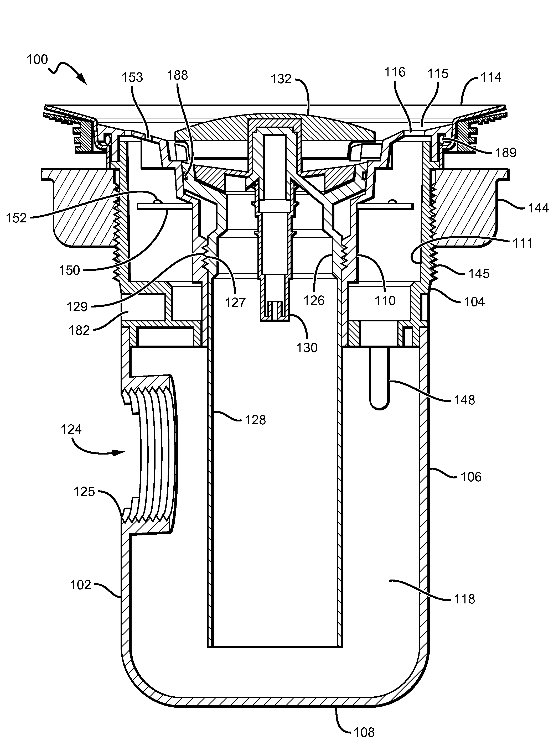
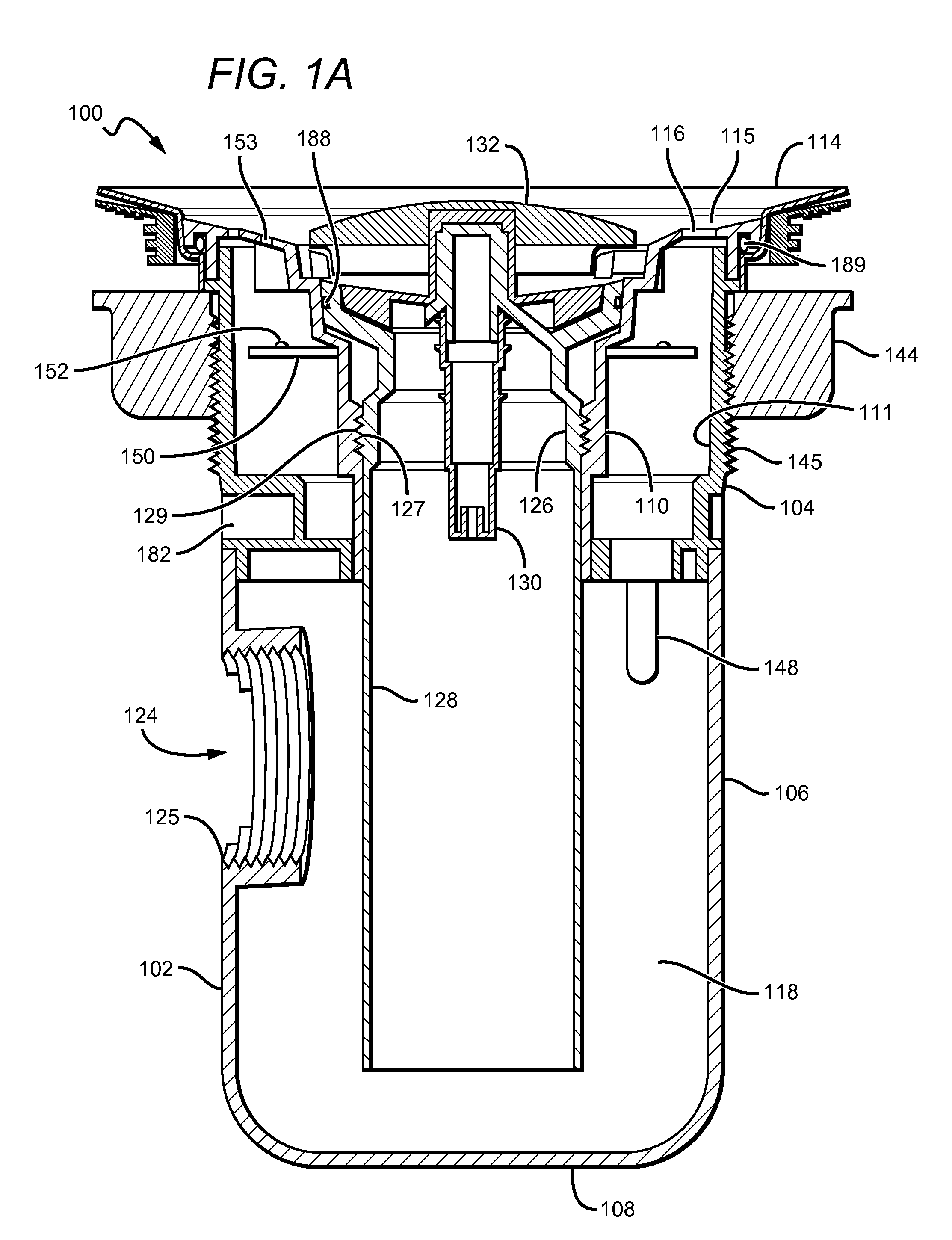
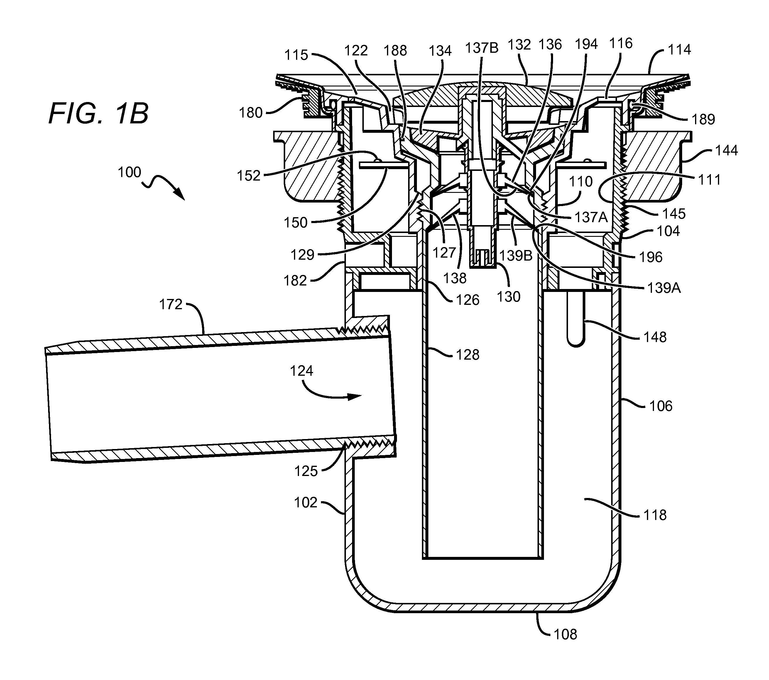
[0046]In FIGS. 1A-1B, a cartridge 100 is shown that regulates a fluid flow and has a housing 102 that comprises an upper housing 104, a lower section 106, and bottom 108. The upper housing 104 can comprise inner and outer portions 110 and 111, respectively, although it is contemplated that the upper housing 104 can comprise a single piece. The upper housing 104 and the lower section 106 of the housing 102 can be fixedly coupled by one or more fastener(s) including, for example, adhesive or other glues, threads or other mechanical fasteners, and combination(s) thereof. Insert 126 can be at least partially disposed within the upper housing 104, and configured to be user-removable from the upper housing 104. Each of the upper housing 104, the insert 126, and the lower section 106 can be composed of any commercially suitable material(s) including, for example, plastics and other polycarbonates, metal, quartz, porcelain, and any combination(s) thereof.

[0047]Cartridge 100 is preferably si...


PUM


Abstract

Various embodiments of a cartridge for regulating a fluid flow are described that include an upper housing, and an insert that is user-removable from the upper housing. The cartridge can include one or more valves that are biased in a closed position to prevent odors from escaping the cartridge. The cartridge can also include a fluid trap that is at least partially disposed within the cartridge or fluidly coupled thereto. An ultraviolet light can be inserted within the cartridge to disinfect a fluid passageway of the cartridge.

Description

[0001]This application is a continuation-in-part of U.S. utility application of 12 / 765,123 filed Apr. 22, 2010 which claims priority to U.S. provisional applications having Ser. No. 61 / 175,705 filed on May 5, 2009, Ser. No. 61 / 175,831 filed on May 6, 2009, Ser. No. 61 / 177,150 filed on May 11, 2009, Ser. No. 61 / 262,981 filed on Nov. 20, 2009, and Ser. No. 61 / 289,633 filed on Dec. 23, 2009.[0002]This application is also a continuation-in-part of U.S. patent application Ser. No. 12 / 154,891 filed on May 28, 2008, which claims priority to U.S. provisional patent application with Ser. No. 60 / 932,700 filed on Jun. 1, 2007. These and all other extrinsic materials discussed herein are incorporated by reference in their entirety. Where a definition or use of a term in an incorporated reference is inconsistent or contrary to the definition of that term provided herein, the definition of that term provided herein applies and the definition of that term in the reference does not apply.FIELD OF T...

Claims


Application Information

Patent Timeline
Patent Type & Authority Applications(United States)
IPC IPC(8): E03C1/12E03D13/00
CPCC02F1/325C02F2201/3223C02F2201/326E03C1/298E03C1/126E03D13/00C02F2209/40
Inventor FIMA, GIOVANNI
Owner GREEN DRAIN
Why Eureka
Try Eureka