Current detector and wattmeter using the same
a current detector and wattmeter technology, applied in the field of current detectors, can solve the problems of high cost, inaccurate measurement of current magnitude, and increase in the size of current detectors, and achieve the effects of small and inexpensive configuration, improved detection sensitivity, and accurate measuremen
- Summary
- Abstract
- Description
- Claims
- Application Information
AI Technical Summary
Benefits of technology
Problems solved by technology
Method used
Image
Examples
example 1
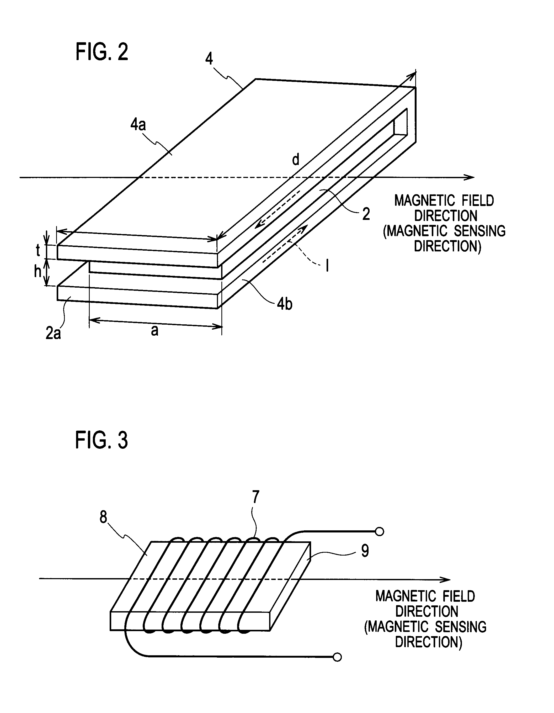
[0030]A current detector according to Example 1 of the present invention illustrated in FIG. 2 includes a plate-like conductor 4 having a predetermined width w1 is folded approximately in the middle in a longitudinal direction so as to have an upper conductor 4a and a lower conductor 4b parallel to and facing each other having a gap h therebetween. Thus, a current path 2a formed into a loop (hereinafter, referred to as a looped current path) is obtained in the conductor 4. Alternatively, a method of cutting in the conductor 4 may be used to form the looped current path.
[0031]A magneto-electric transducer 2 is placed in a center portion in the gap between the upper conductor 4a and the lower conductor 4b, namely in a center portion of the looped current path 2a. The magneto-electric transducer 2 is to have detection sensitivity with respect to a direction of a magnetic field (a right direction in FIG. 2) that is generated by a flow of the current to be detected I in the looped curren...
example 2
[0043]FIG. 9 illustrates a configuration of a current detector according to Example 2 of the present invention. FIG. 9(a) is an external perspective view, FIG. 9(b) is a plan view, FIG. 9(c) is a side view, and FIG. 9(d) is a front view. The current detector according to Example 2 of the present invention illustrated in FIG. 2 includes a U-shaped plate-like conductor 5 having a predetermined width w2. The conductor 5 is folded approximately in the middle in a longitudinal direction so as to have an upper conductor and a lower conductor parallel to and facing each other having the gap h therebetween. Thus, a first looped current path 3a is formed in a first conductor 5a having a predetermined width w1. Similarly, a second looped current path 3b is formed in a second conductor 5b having the predetermined width w1.
[0044]The U-shaped plate-like conductor 5 is folded in half so as to form the first conductor 5a and the second conductor 5b, which are connected with each other at a bottom ...
PUM
 Abstract
Description
Claims
Application Information
 - R&D
- Intellectual Property
- Life Sciences
- Materials
- Tech Scout
- Unparalleled Data Quality
- Higher Quality Content
- 60% Fewer Hallucinations
Browse by: Latest US Patents, China's latest patents, Technical Efficacy Thesaurus, Application Domain, Technology Topic, Popular Technical Reports.
© 2025 PatSnap. All rights reserved.Legal|Privacy policy|Modern Slavery Act Transparency Statement|Sitemap|About US| Contact US: help@patsnap.com


