Apparatus and Method for Power Distribution to and Cooling of Computer Components on Trays in a Cabinet

a technology for computer components and cabinets, applied in the direction of electrical apparatus casings/cabinets/drawers, instruments, computing, etc., can solve the problems of cumbersome computers, inconvenient service and/or upgrade components of these computers, and the need to take out the entire computer. , to achieve the effect of reducing distance and reducing distan

Inactive Publication Date: 2011-01-20
SILICON GRAPHICS INT CORP
View PDF4 Cites 71 Cited by
  • Summary
  • Abstract
  • Description
  • Claims
  • Application Information

AI Technical Summary

Benefits of technology

[0008]In another innovative aspect, the invention relates to a computer system comprising a cabinet, a first plurality of trays located in an upper portion of the cabinet and having a first plurality of computer components mounted thereon, a second plurality of trays located in a lower portion of the cabinet and having a second plurality of computer components mounted thereon, a first AC-to-DC power conversion module, a second AC-to-DC power conversion module, a first DC power distribution bar coupling the first AC-to-DC power conversion module to the first plurality of trays, and a second DC power distribution bar coupling the second AC-to-DC power conversion module to the second plurality of trays. The first AC-to-DC power conversion module is mounted on the upper portion of the cabinet, and is posi

Problems solved by technology

Many of the racks are filled with cumbersome computers mounted on sliders, which are attached through mounting holes provided in the front and back of the rack.
It can be inconvenient to service and/or upgrade components of these computers because a computer may need to be dismounted from a rack, and a portion of the chassis housing the computer may need to be disassembled.
In addition, to service and/or upgrade a component of these

Method used


Image

  • Apparatus and Method for Power Distribution to and Cooling of Computer Components on Trays in a Cabinet
  • Apparatus and Method for Power Distribution to and Cooling of Computer Components on Trays in a Cabinet
  • Apparatus and Method for Power Distribution to and Cooling of Computer Components on Trays in a Cabinet

Examples


Embodiment Construction

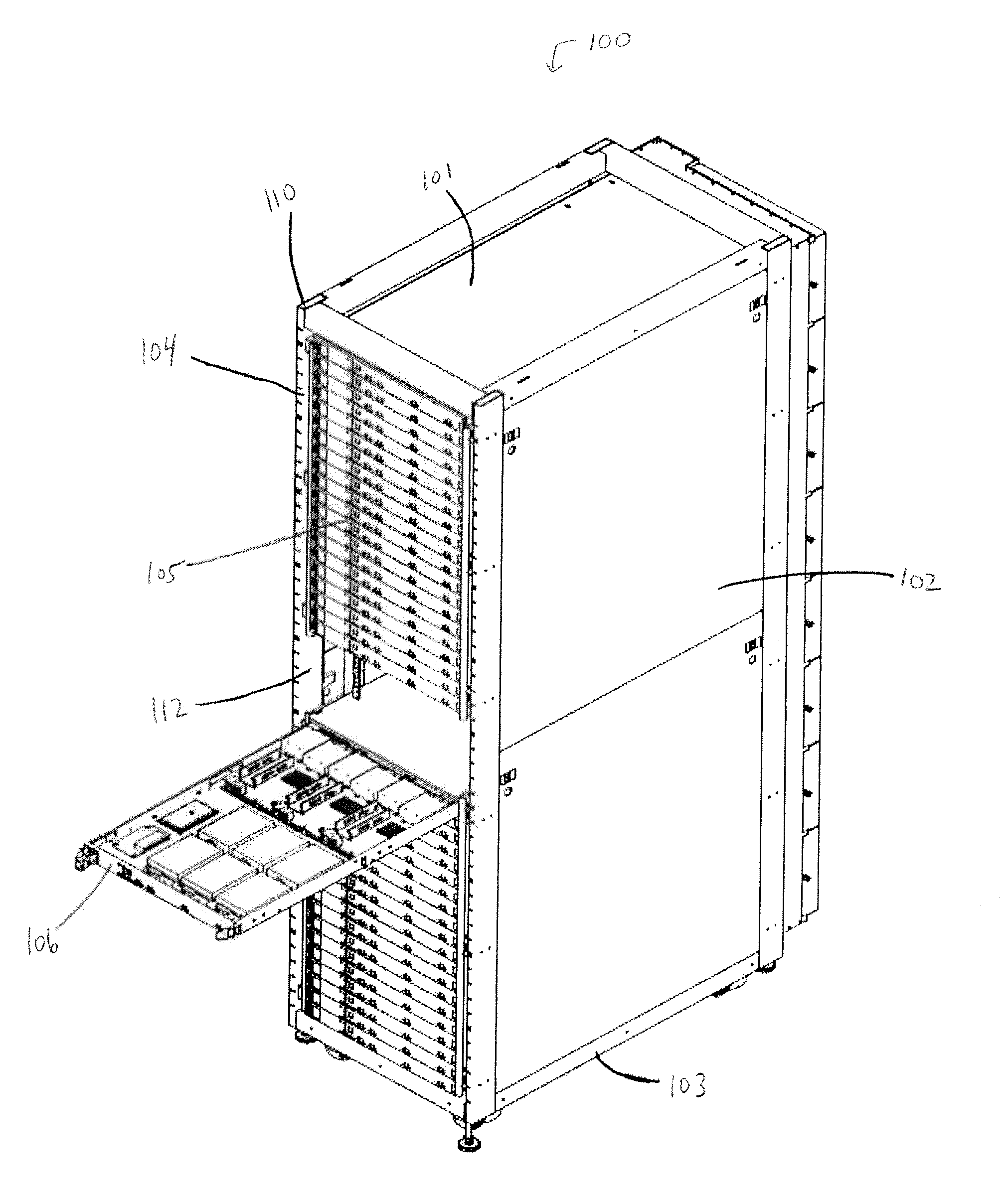
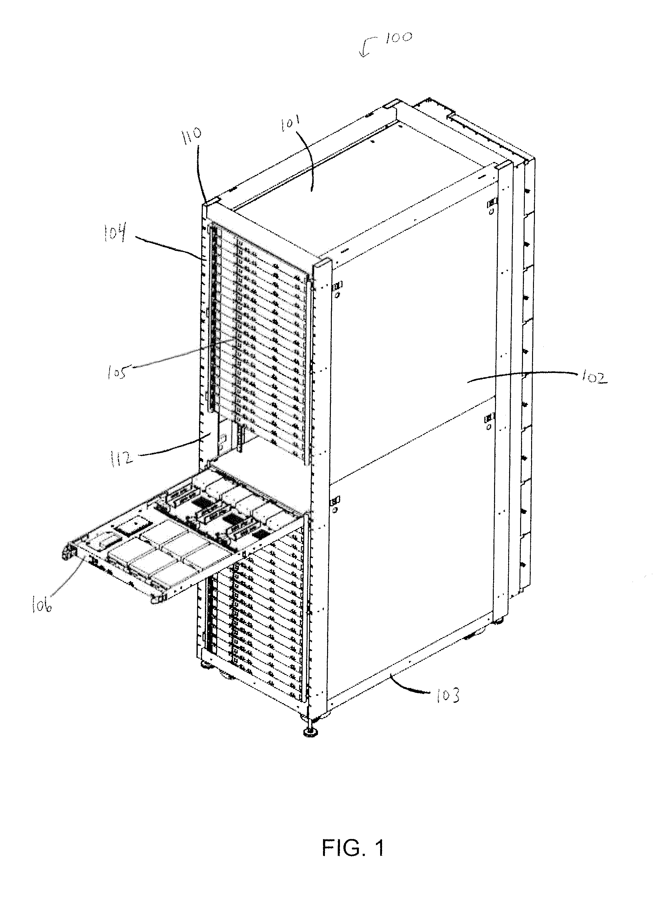
[0015]FIG. 1 illustrates a front perspective view of a computer system 100 including a cabinet 110 and trays 105 mounted in the cabinet 110, in accordance with one embodiment of the present invention. The cabinet 110 has a top panel 101, side panels 102, and a bottom panel 103. Trays 105 have front panels 106 that face outward from a front side 104 of the cabinet 110. The front side 104 of the cabinet 110 may at least partially expose front panels 106 of trays 105. In one embodiment, the front side 104 of the cabinet 110 may not be covered with a front panel to facilitate access to the trays 105, such as for servicing or replacement of the trays 105. The exposure of the front panels 106 also enhances airflow from outside the cabinet 110 toward the front panels 106 of the trays 105, or the reverse, for cooling computer components mounted on the trays 105. Alternatively, the front side 104 of the cabinet 110 may be covered with a front panel (not shown). The front panel may be used to...


PUM


Abstract

A computer system includes a cabinet, a plurality of trays located in the cabinet and having a plurality of computer components mounted thereon, a first port mounted on a rear panel of the cabinet that receives a three-phase AC input to the cabinet, a power distribution unit that converts the three-phase AC input to a plurality of AC signals each having fewer than three phases, a plurality of rectifiers, and a power distribution bus. The plurality of rectifiers convert the plurality of AC signals to DC power. The power distribution bus distributes the DC power. Each of the plurality of rectifiers is coupled to the power distribution bus. The tray receives the DC power from the power distribution bus.

Description

CROSS-REFERENCE TO RELATED APPLICATIONS[0001]This application claims the benefit of U.S. provisional patent application No. 61 / 161,033, entitled “APPARATUS AND METHOD FOR POWER DISTRIBUTION TO AND COOLING OF COMPUTER COMPONENTS ON TRAYS IN A CABINET” filed on Mar. 17, 2009, which is incorporated herein by reference in its entirety.FIELD OF THE INVENTION[0002]The present invention relates generally to the manner in which computer components are designed, configured, and installed in a given area. More particularly, this invention relates to power distribution to and cooling of computer components mounted on trays in a cabinet.BACKGROUND OF THE INVENTION[0003]As information technology has rapidly progressed, computer network centers such as server farms and server clusters have become increasingly important to our society. The server farms provide efficient data processing, storage, and distribution capability that supports a worldwide information infrastructure, which has come to alt...

Claims


Application Information

Patent Timeline
IPC IPC(8): G06F1/16
CPCG06F1/20G06F1/189
Inventor SEIBOLD, LAWRENCE B.COGLITORE, GIOVANNIKINSTLE, III, ROBERT M.
Owner SILICON GRAPHICS INT CORP
Why Eureka
Try Eureka