Passive optical network (PON) in-band optical time domain reflectometer (OTDR)

a passive optical network and reflectometer technology, applied in the field of sensing, can solve problems such as difficult to see what happens after a split, difficult to implement otdr in pons, and difficult to locate failures or degradations of physical plants

Active Publication Date: 2011-01-20
MICROSEMI ISRAEL STORAGE SOLUTIONS LTD
View PDF12 Cites 101 Cited by
  • Summary
  • Abstract
  • Description
  • Claims
  • Application Information

AI Technical Summary

Problems solved by technology

The fiber links can be in rural areas, and are often buried, making locate failures or degradations of this physical plant a hard task.
Implementing OTDR in PONs is challenging for conventional OTDR test equipment.
As a result of the high loss from splitters and the fact that reflected signals see this loss in both forward and backward propagation, the OTDR signals are strongly attenuated, resulting in difficulty in seeing what happens after a split.
In addition, a PON has an additional complication—a forward propagating probe pulse from an OLT is split by a splitter and sent down all the splitter arms simultaneously.
However, because the signal and backscatter reflections from all ONUs are combined by the splitter as the signal...

Method used


Image

  • Passive optical network (PON) in-band optical time domain reflectometer (OTDR)
  • Passive optical network (PON) in-band optical time domain reflectometer (OTDR)
  • Passive optical network (PON) in-band optical time domain reflectometer (OTDR)

Examples


Embodiment Construction

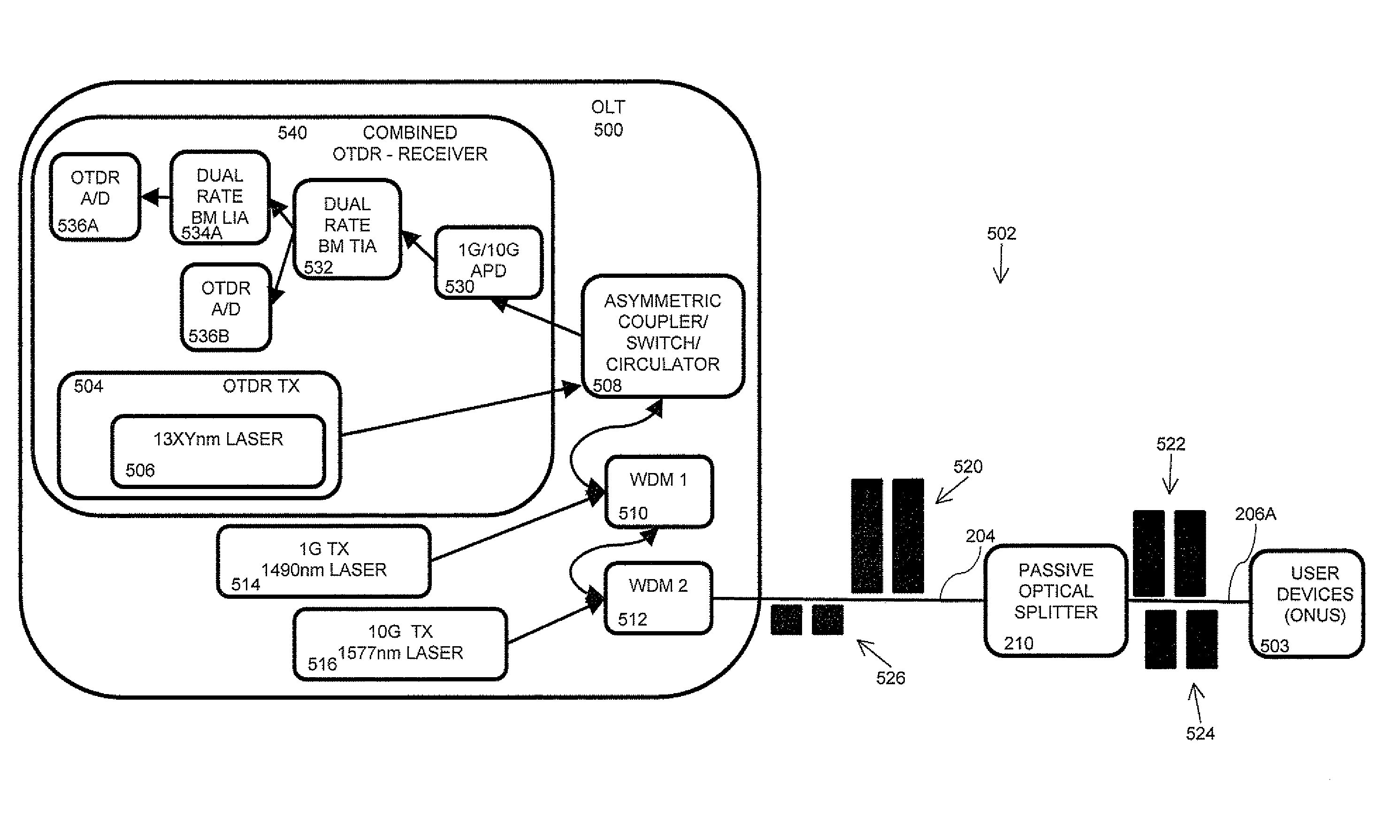
[0045]The principles and operation of the system and method according to the present embodiment may be better understood with reference to the drawings and the accompanying description. The present embodiment is a system for performing analysis of links, in particular optical time domain reflectometry (OTDR) of PONs. The system and method facilitate testing of links more frequently, while maintaining service for users, and at a lower cost than conventional solutions.

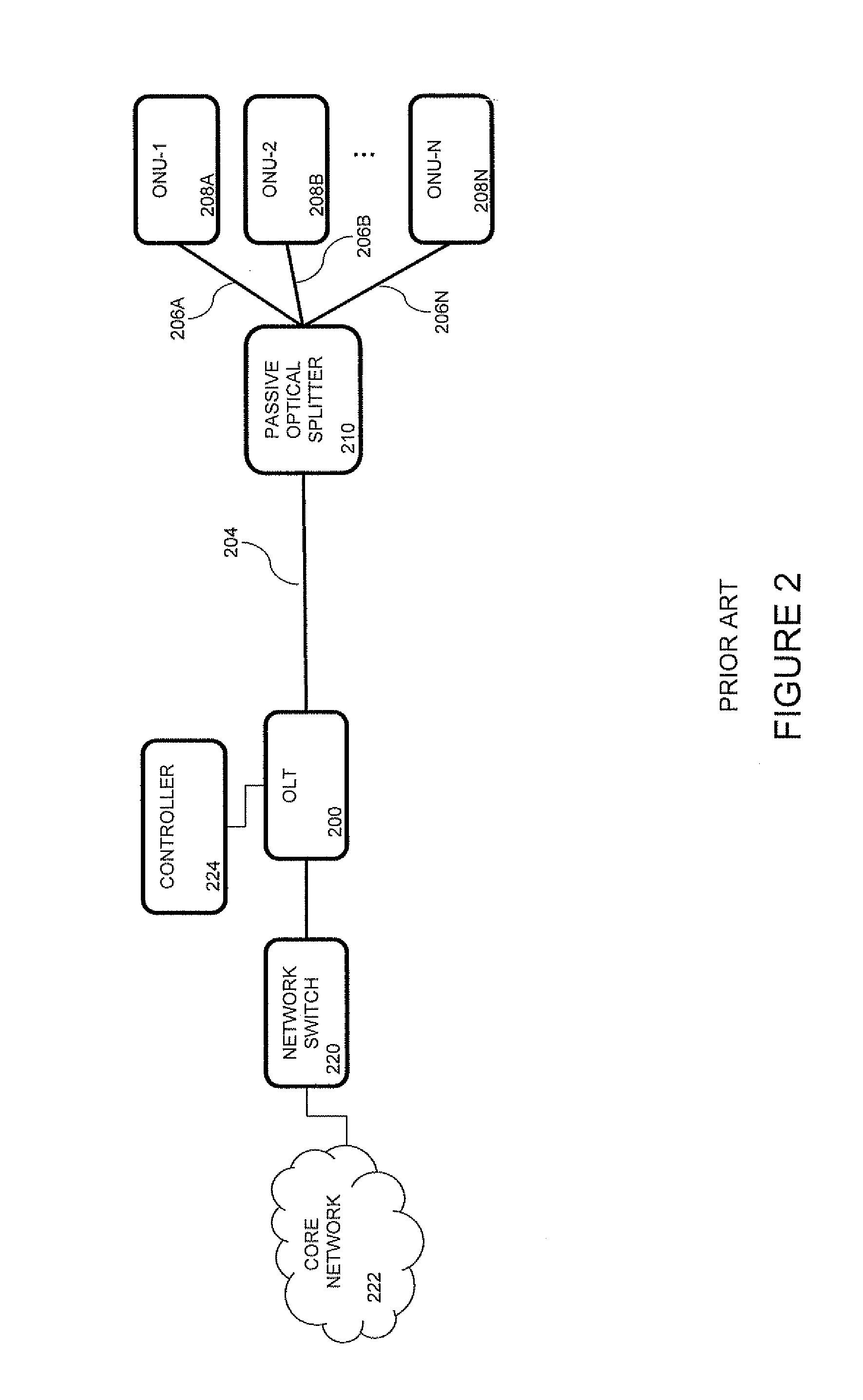
[0046]In one embodiment, an OTDR test uses a network's communication protocols with the data signal transmission wavelength to perform OTDR testing on a link, referred to as in-band OTDR testing. In other words, an OTDR signal (probe pulse) is handled by the network's communication protocol like a network data signal. A network device is typically operationally connected to at least one user device via a link. When an OTDR measurement is to be performed, the network device notifies the user devices to halt transmission o...


PUM


Abstract

An in-band OTDR uses a network's communication protocols to perform OTDR testing on a link. Because the OTDR signal (probe pulse) is handled like a data signal, the time required for OTDR testing is typically about the same as the time required for other global network events, and is not considered an interruption of service to users. A network equipment includes an optical time domain reflectometry (OTDR) transmitter and receiver, each operationally connected to a link to transmit and receive, respectively, an OTDR signal. When an OTDR is to be performed, a network device operationally connected to the link actuates the OTDR transmitter to transmit the OTDR signal on the link during a determined test time based on a communications protocol of the link, during which data signals are not transmitted to the network equipment. A processing system processes the OTDR signal to provide OTDR test results.

Description

CROSS-REFERENCE TO RELATED APPLICATIONS[0001]This application claims the benefit of provisional patent application (PPA) Ser. No. 61 / 225,572 filed on Jul. 15, 2009 by the present inventors, which is incorporated by reference.FIELD OF THE INVENTION[0002]The present embodiment generally relates to sensing, and in particular, it concerns a system and method for optical time domain reflectometry in a passive optical network.BACKGROUND OF THE INVENTION[0003]An Optical Time Domain Reflectometer (OTDR) is a very important tool (or “function”) for characterization and diagnosis of optical links. The general concept of optical time domain reflectometry (also referred with the abbreviation OTDR), is to transmit an optical pulse into an optical link and measure a reflected signal from the link as a function of time. An optical pulse is more specifically known as a probe pulse, and also referred to as a pulse or an OTDR signal. In the context of this document, an optical link is generally an op...

Claims


Application Information

Patent Timeline
IPC IPC(8): H04B10/08H04B10/272
CPCH04B10/071G01M11/3118G01M11/00G01M11/02G01N21/00H04B10/00
Inventor KHERMOSH, LIORLOOK, CHRISTOPHER MICHAELGALAMBOS, TIBERIU
Owner MICROSEMI ISRAEL STORAGE SOLUTIONS LTD
Why Eureka
Try Eureka