Fan exhaust nozzle for turbofan engine

a technology of turbofan and exhaust nozzle, which is applied in the direction of marine propulsion, vessel construction, aircraft navigation control, etc., can solve the problem of shifting in the direction of net thrust produced, and achieve the effect of improving the operational cos

Active Publication Date: 2011-01-20
RTX CORP
View PDF8 Cites 12 Cited by
  • Summary
  • Abstract
  • Description
  • Claims
  • Application Information

AI Technical Summary

Benefits of technology

[0009]To accommodate this imbalance in fan flow through the fan duct caused by the obstruction offered by the pylon's presence in the fan duct, in accordance with the present invention, that portion of the fan duct through which the pylon extends, on one side of a central plane of the engine, is made larger than that portion of the fan duct on the opposite side of the central plane to make up for the restriction to fan air flow caused by the pylon. In a preferred embodiment, the difference in area between the two fan duct cross sectional areas at a downstream portion thereof (i.e., at the fan exhaust nozzle) is equal to the cross sectional area of the pylon presented to the flow through the fan duct. This difference in area essentially eliminates the shift in the direction of the net thrust produced by the engine for optimal (minimal) fuel consumption in the face of the restriction caused by the pylon.
[0011]It is estimated that the asymmetric distribution of the fan duct flow area at the fan exhaust nozzle thereof will result in up to an approximate improvement of up to 0.5% in total specific fuel consumption which, when taken in the context of modem commercial aircraft consumption of hundreds of thousands of gallons of fuel on an annual basis, represents a significant improvement in the operational costs associated with such engine.

Problems solved by technology

This imbalance in the fan flow, between the two opposed portions of the fan duct, results in a shift in the direction of the net thrust produced by the fan from a direction parallel to the center longitudinal axis of the engine.

Method used


Image

  • Fan exhaust nozzle for turbofan engine
  • Fan exhaust nozzle for turbofan engine
  • Fan exhaust nozzle for turbofan engine

Examples


Embodiment Construction

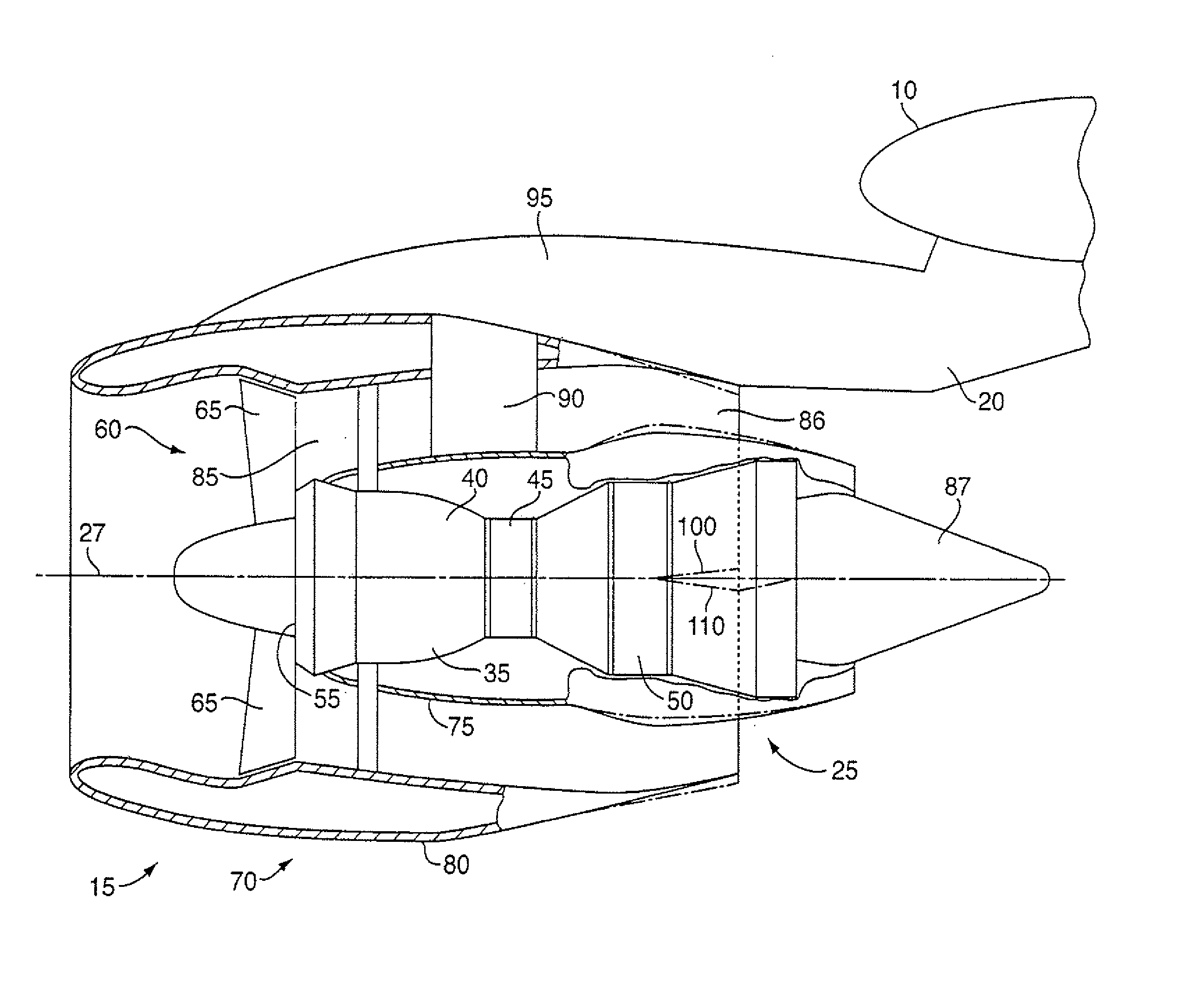
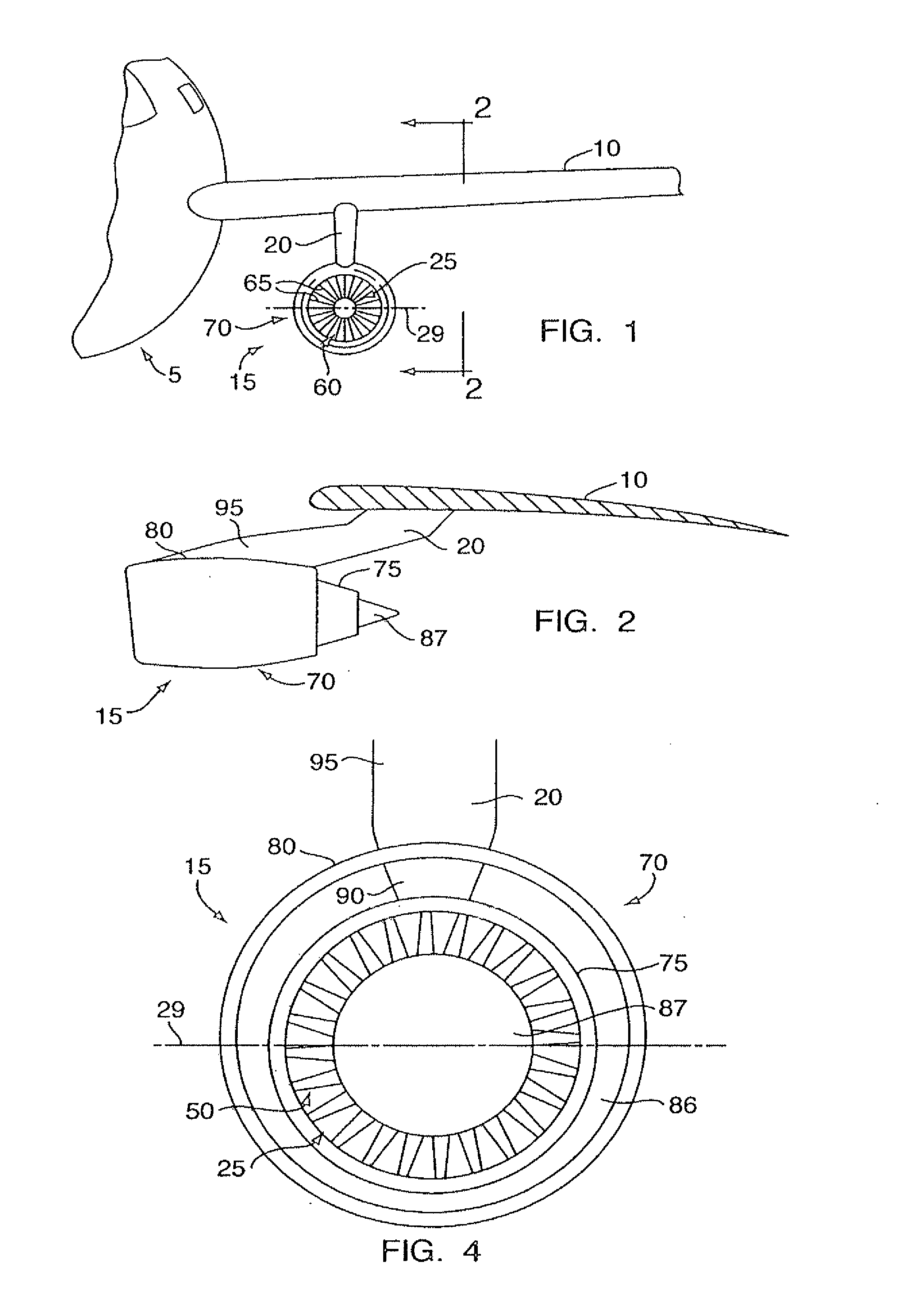
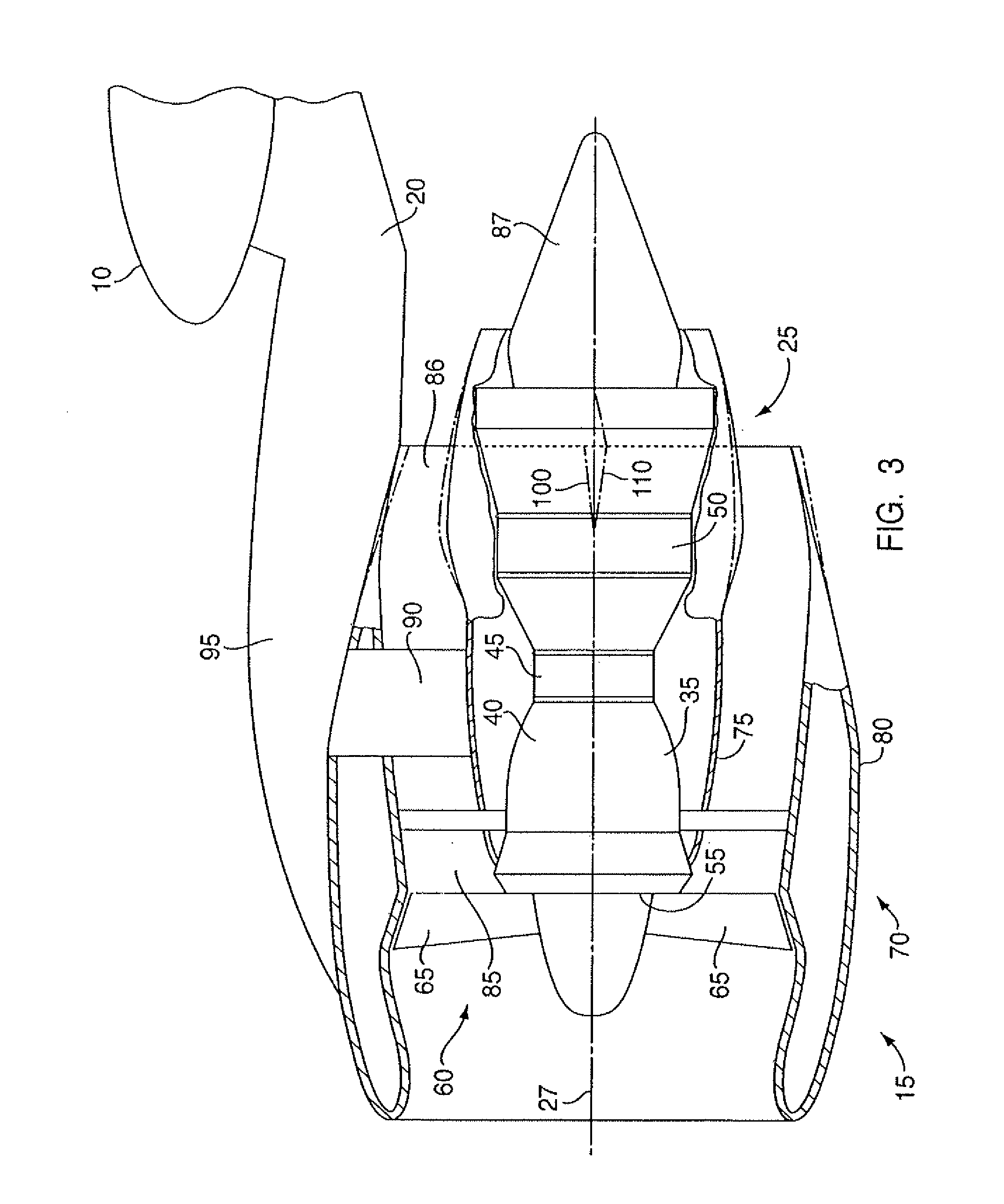
[0016]Referring to FIGS. 1 and 2, a commercial gas turbine engine powered aircraft includes a wing 10 having one or more gas turbine engine power plants 15 mounted on the underside thereof by a pylon 20. As best seen in FIG. 3, gas turbine engine power plant 15 comprises a gas turbine engine 25 characterized by a longitudinal central axis 27 which lies in a horizontal (under normal operating conditions) central plane 29 of the engine. In a manner well known in the art, gas turbine engine 25 includes a case 35 enclosing a compressor 40 (not shown), a combustor 45 (not shown), and a turbine 50 (also not shown), the details of which are well known in the art. As is also well known in the art, air entering compressor 40 through inlet 55 is compressed in the compressor, and enters the combustor where it is mixed with jet fuel and burned, the products of combustion (working fluid) flowing into turbine 50 which extracts energy therefrom to drive the compressor and provide thrust for poweri...


PUM


Abstract

The cross sectional flow area of a fan discharge nozzle on one side of a central plane of an associated gas turbine engine power plant is greater than the corresponding flow area of the fan discharge nozzle on an opposite side of the central plane to compensate for the blockage of fan airflow by a pylon.

Description

RELATED APPLICATION[0001]This application is a divisional application of U.S. patent application Ser. No. 11 / 513,707, filed on Aug. 31, 2006.BACKGROUND OF THE INVENTION[0002]This invention relates generally to aircraft gas turbine engines and particularly to turbofan gas turbine engines.[0003]The operation of turbofan gas turbine aircraft engines is well known. Such engines include a serial arrangement of a fan, a compressor, a combustor and a turbine (the compressor, combustor and turbine comprising a “core engine”). Air admitted into the inlet of the engine is compressed by the engine's compressor. The compressed air is then mixed with fuel in the engine's combustor and burned. The high-energy products of combustion of the burned airfuel mixture then enters the turbine with extracts energy from the mixture in order to drive the compressor and fan. That energy extracted by the turbine above and beyond that necessary to drive the compressor and fan, exits the engine at the core engi...

Claims


Application Information

Patent Timeline
Patent Type & Authority Applications(United States)
IPC IPC(8): F01D5/04
CPCF01D25/28F02K3/06F02K1/78
Inventor MCCALL, JOHN
Owner RTX CORP
Why Eureka
Try Eureka