Mixing and/or evaporating device

a technology of evaporation device and exhaust system, which is applied in the direction of flow mixer, mixer, mechanical apparatus, etc., can solve the problems of low flow resistance during flow, and achieve the effects of large dimensions, low cost, and sufficient opaqueness

Active Publication Date: 2011-01-27
EBERSPACHER EXHAUST TECH GMBH & CO KG
View PDF4 Cites 23 Cited by
  • Summary
  • Abstract
  • Description
  • Claims
  • Application Information

AI Technical Summary

Benefits of technology

[0011]Corresponding to another advantageous embodiment, the blades have relatively large dimensions in the axial direction, as a result of which a sufficient opaqueness can be achieved in the axial direction between the leading edge and the discharge edge even in case of a comparatively small angle of incidence. In particular, the axial length of a blade, multiplied by the number of blades, is greater than the circumferential length of the outer wall, from which the blades project towards the inside.
[0012]Corresponding to an advantageous variant, the mixing and/or evaporating device may be manufactured from a single sheet metal part by forming.

Problems solved by technology

This leads to a low flow resistance during the f

Method used


Image

  • Mixing and/or evaporating device
  • Mixing and/or evaporating device
  • Mixing and/or evaporating device

Examples


Embodiment Construction

[0028]Referring to the drawings in particular, the absolute numerical data given above and below for dimensions and angles are always defined within the framework of the usual manufacturing tolerances.

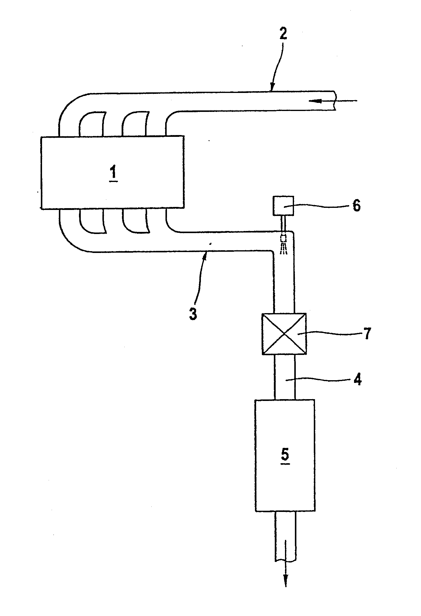
[0029]Corresponding to FIG. 1, an internal combustion engine 1, which may be arranged, for example, in a motor vehicle, has a fresh gas system 2 for supplying with fresh gas, preferably air, and an exhaust system 3 for removing exhaust gas. Such an exhaust system 3 comprises an exhaust gas-carrying line 4, which removes the exhaust gas generated at the internal combustion engine from the internal combustion engine 1 during the operation of said internal combustion engine. The exhaust system 3 may have at least one exhaust gas-treating device 5, which is integrated in the exhaust gas-carrying line 4. This exhaust gas-treating device 5 may be, for example, an oxidation-type catalytic converter, an NOx storage catalyst, a hydrolysis reactor, an SCR catalytic converter or a particle filter...


PUM

PropertyMeasurementUnit
Angleaaaaaaaaaa
Angleaaaaaaaaaa
Angleaaaaaaaaaa

Abstract

A mixing and/or evaporating device (7) is provided through which exhaust gas can flow axially. The mixing and/or evaporating device (7) is arranged in an exhaust gas-carrying line of an exhaust system of an internal combustion engine, especially of a motor vehicle, with a plurality of blades (8), which are arranged distributed in the circumferential direction and which project inwardly from an outer wall (9). Each blade (8) has a profile (10) at least in an area adjoining the outer wall (9) in the axial direction (14), in which profile a discharge edge (12) has an offset (16) in the circumferential direction (15) in relation to the leading edge (11). A reduction of the flow resistance of the device (7) can be achieved if the profile (10) has an angle of incidence (17) each in relation to the axial direction (14) at the leading edge (11) and at the discharge edge (12), which angle is in a range of −10°, inclusive to +10°, inclusive.

Description

CROSS REFERENCE TO RELATED APPLICATIONS[0001]This application claims the benefit of priority under 35 U.S.C. §119 of German Patent Application DE 10 2009 034 670.8 filed Jul. 25, 2009, the entire contents of which are incorporated herein by reference.FIELD OF THE INVENTION[0002]The present invention pertains to a mixing and / or evaporating device for an exhaust system, especially of a motor vehicle. The present invention pertains, moreover, to an exhaust system equipped with such a mixing and / or evaporating device.BACKGROUND OF THE INVENTION[0003]For various reasons, it may be necessary in exhaust systems of internal combustion engines to introduce a liquid educt into the exhaust gas flow. For example, fuel may be injected into the exhaust gas flow upstream of an oxidation-type catalytic converter in order to trigger an exothermal combustion reaction at the oxidation-type catalytic converter arranged downstream. For example, a reducing agent, for example, ammonia, may likewise be inj...

Claims


Application Information

Patent Timeline
IPC IPC(8): F01N3/02
CPCB01F3/04021B01F5/0451B01F5/0616Y02T10/24F01N3/2066F01N3/2892B01F2005/0636Y02A50/20Y02T10/12B01F23/213B01F25/3131B01F25/4315B01F25/431971
Inventor WIRTH, GEORG
Owner EBERSPACHER EXHAUST TECH GMBH & CO KG
Why Eureka
Try Eureka