Spark plug

Active Publication Date: 2011-01-27
NGK SPARK PLUG CO LTD
View PDF12 Cites 3 Cited by
  • Summary
  • Abstract
  • Description
  • Claims
  • Application Information

AI Technical Summary

Benefits of technology

[0011]In the spark plug of the invention according to claim 1, since the following formula is satisfied: H≧1.8 mm, and the following formulae are satisfied: 4.02 mm3<Vi≦12.51 mm3, 2.10 mm3≦Vc≦6.42 mm3, and Vc/Vi≦1.03, it is possible to speedily increase the temperature of the insulator. In general, the smaller the volume Vc of the insulator, the more the effect on carbon fouling can be recognized; however, since the temperature of the insulator around the ignition portion rises, the durability of the insulator deteriorates. In the invention, by using spark plugs with Vc exhibiting excellent recovery of carbon fouling, optimum numeral ranges of H, Vi, Vc, and Vc/Vi were found out by evaluating the durability of insulators in an engine and evaluating the durability of center electrodes. In consequence, since it is possible to speedily increase the temperature of the insulator, it is possible to speedily burn off the carbon adhered on the insulator. Further, as the carbon is speedily burned off, high advantages are exhibited in the prevention of occurrence of the creeping discharge such as side sparks and in securing insulation resist

Problems solved by technology

However, if the spark plug becomes smaller in diameter, the insulation distance between the insulator and the metal shell becomes narrow.
As a result, the spark plug fails to discharge sparks in a regular spark discharge gap, and side sparks are prone to be generated from the center electrode to the me

Method used


Image

  • Spark plug
  • Spark plug
  • Spark plug

Examples


example 1

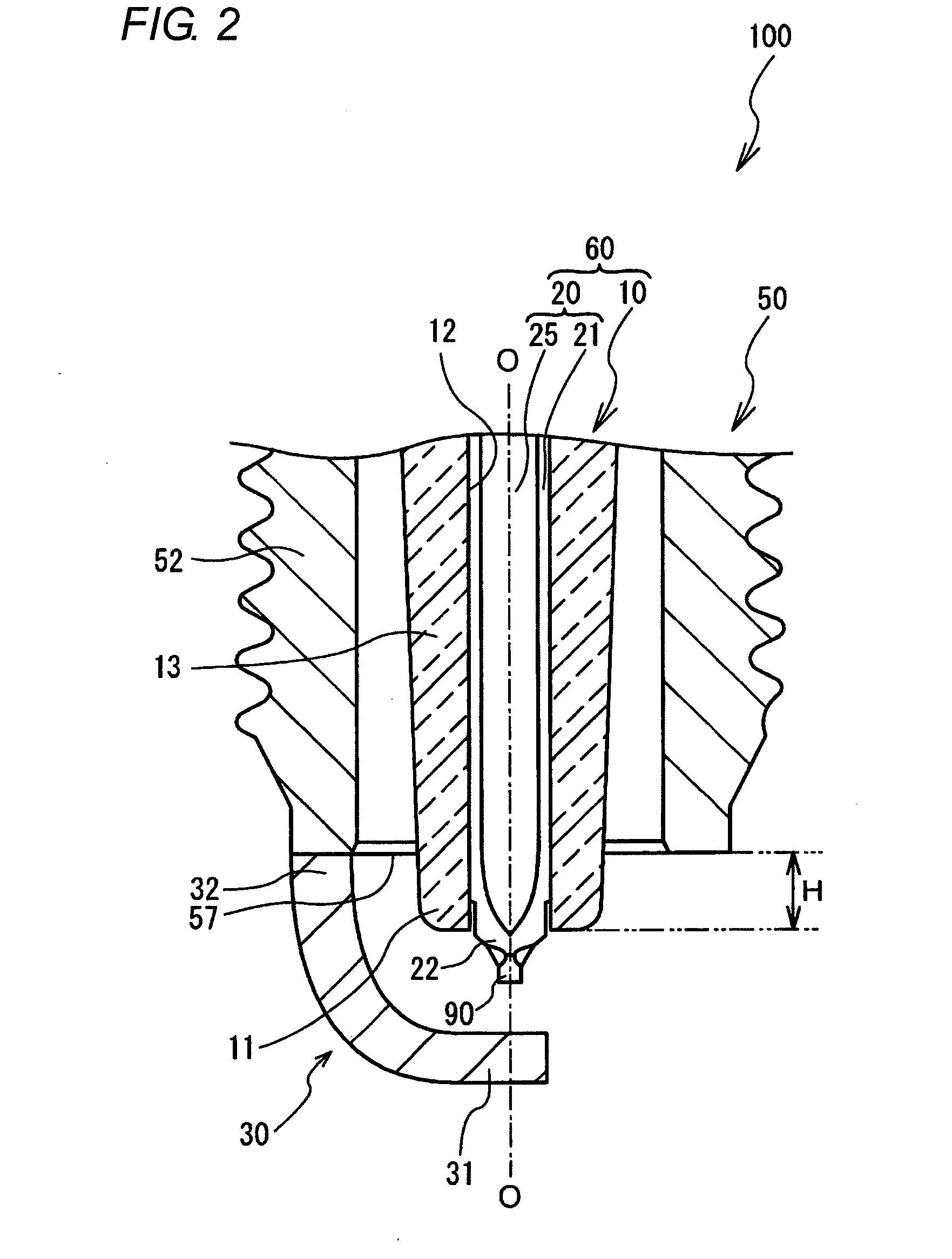
[0059]In Example 1, the effect of H, Vi, and Vc exerted on the recovery property of carbon fouling was examined. First, in this test, four test sections in which H of the insulator differed were provided. Settings were provided such that H=0.8 mm for test section 1, H=1.8 mm for test section 2, H=2.8 mm for test section 3, and H=3.8 mm for test section 4. Pluralities of spark plugs, which satisfied H set for each test section and in which Vi and Vc were respectively varied appropriately, were respectively prepared for the respective test sections.

[0060]Next, a description will be given of the test conditions. First, spark plugs were dry-fouled on the basis of the dry fouling test of JIS D 1606 to prepare spark plugs with an insulation resistance value of 100Ω. Then, each spark plug with its insulation resistance value adjusted was mounted in an engine on a bench, and was held for two minutes under the conditions of the engine speed of 3000 rpm and the intake pressure of −30 MPa. Sub...

example 2

[0070]In Example 2, a withstand voltage test of insulators was conducted in the numerical ranges defined in Example 1. First, spark plugs which satisfied the respective ranges of H and Vi, which were excellent in the recovery property at the time of fouling in Example 1, were fabricated as samples. Specifically, 23 samples were fabricated by setting, as for H, three kinds, 1.8, 2.8, and 3.8, and by appropriately varying Vi in the range of 2.47 to 12.51 (mm3). It should be noted that the spark discharge gap was adjusted to 1.3 mm by taking electrode wear into consideration.

[0071]Next, a description will be given of the test conditions. As the engine, a 660 cc 3-cylinder turbocharged engine was used. As for the test pattern, the pattern consisted of 1 minute of idling (800 rpm) and 3 minutes at wide open throttle, and this pattern was repeated for 10 hours. Then, with respect to the respective samples after 10 hours, the recovery property of fouling was evaluated, and the voltage resi...

example 3

[0074]In Example 3, the effect of Vc exerted on the durability of the electrode tip welded to the front end portion of the center electrode was examined. In the durability test of the electrode tips, the residual ratio of the electrode tip after 100 hours of the durability test with the spark plug mounted in the engine was calculated. Here, the term “residual ratio” refers to the residual ratio of a portion of the electrode tip which does not include a molten portion, and was calculated by the following formula:

Residual ratio=(volume of electrode tip after durability test) / (volume of electrode tip before durability test)

[0075]It should be noted that the term “volume of electrode tip” refers to the volume of a portion of the electrode tip which does not include a molten portion.

[0076]Next, a description will be given of the test conditions. As the engine, a 2 L 4-cylinder engine was used. Then, a durability test was conducted continuously at WOT (5000 rpm) for 100 hours, and the resi...


PUM


Abstract

A spark plug is provided capable of speedily burn off carbon adhered on an insulator. With this spark plug, in order to improve the temperature rise performance of a front end side of an insulator 10, an amount of protrusion H (mm) of the insulator 10, a front-end side volume Vi (mm3) of the insulator 10, and a front-end side volume Vc (mm3) of a center electrode 20 are respectively defined. In consequence, it is possible to improve the recovery property of carbon fouling while retaining the voltage resistance of the insulator 10 and the durability of the center electrode 20. In addition, since the recovery property of carbon fouling improves, it is possible to prevent the occurrence of side sparks generated from the center electrode 20 to a metal shell 50 along the insulator 10, thereby making it possible to stably ensure proper ignition of an air-fuel mixture.

Description

TECHNICAL FIELD[0001]The present invention relates to a spark plug which is incorporated in an internal combustion engine to ignite an air-fuel mixture.BACKGROUND ART[0002]Conventionally, a spark plug for ignition is used in an internal combustion engine. A spark plug in general includes: a center electrode; an insulator for holding the center electrode in an axial hole; a metal shell for holding the insulator by surrounding its radial periphery; and a ground electrode having one end portion joined to the metal shell and the other end portion, a spark discharge gap being formed between the other end portion and the center electrode. Further, as spark discharge is generated in the spark discharge gap, the ignition of an air-fuel mixture is ignited.[0003]In recent years, it has become necessary to enlarge valve diameters of an intake valve and an exhaust valve which are provided in an engine for a higher engine output, and to secure a larger water jacket for the engine to improve a wa...

Claims


Application Information

Patent Timeline
IPC IPC(8): H01T13/20
CPCH01T13/14
Inventor SUZUKI, AKIRAKATO, TOMOAKI
Owner NGK SPARK PLUG CO LTD
Why Eureka
Try Eureka