Thermal energy storage vessel, systems, and methods

a technology of thermal energy storage and energy storage tanks, applied in the field of energy storage, can solve the problems of requiring a disruptive thawing process step to restart the system, the solution does not produce any power, and the problem of requiring a disruptive thawing process step to achieve the effect of a single tank

Inactive Publication Date: 2011-01-27
BELL INDEPENDENT POWER CORP
View PDF15 Cites 33 Cited by
  • Summary
  • Abstract
  • Description
  • Claims
  • Application Information

AI Technical Summary

Problems solved by technology

Unfortunately, when the sun or wind is not available, such solutions are not producing any power.
Similar issues arise for wind turbines during calm weather.
While this system takes advantage of a vertical temperature gradient within the thermocline tank to enable simplification to a single tank, challenges with respect to the pumping, valving, and delivery of molten salt through a complex network of piping to the solar field, and to the power generator remain present.
The handling of heat transfer fluid by standard pumps, valves and piping is much simpler than the equivalent handling of a molten inorganic salt, which is corrosive, and which is abrasive if some portion of solid phase salt (crystals) is present, and which can solidify in the pumps, valves, and piping at temperatures lower than 400° F., thus requiring a disruptive thawing process step to restart the system.
This simplification notwithstanding, the problems of containing the molten salt, and transferring thermal energy to and from it are significant, particularly at the scale needed by a public utility for an economically viable thermal energy storage process.

Method used


Image

  • Thermal energy storage vessel, systems, and methods
  • Thermal energy storage vessel, systems, and methods
  • Thermal energy storage vessel, systems, and methods

Examples


Embodiment Construction

[0061]For a general understanding of the present invention, reference is made to the drawings. In the drawings, like reference numerals have been used throughout to designate identical elements.

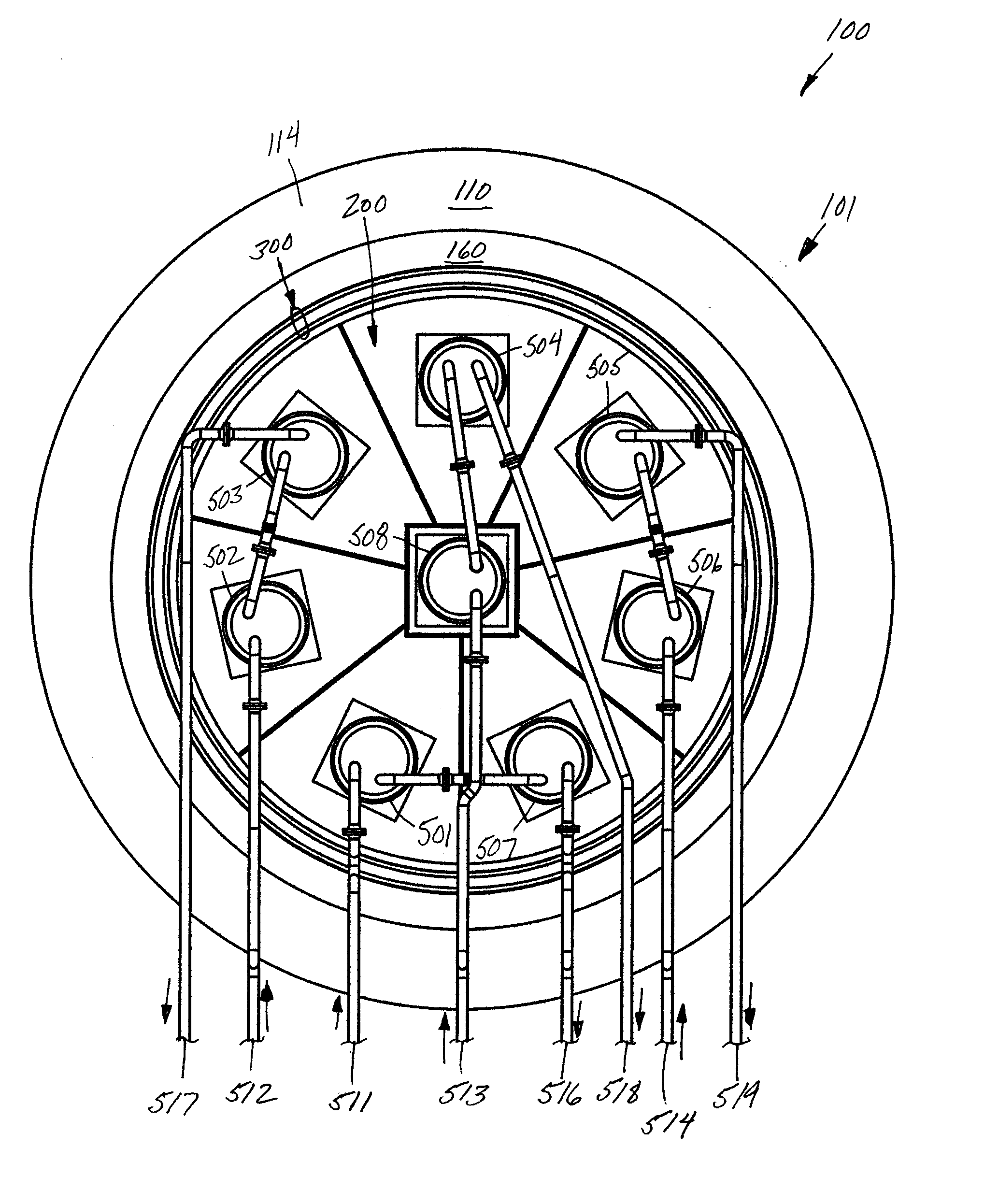
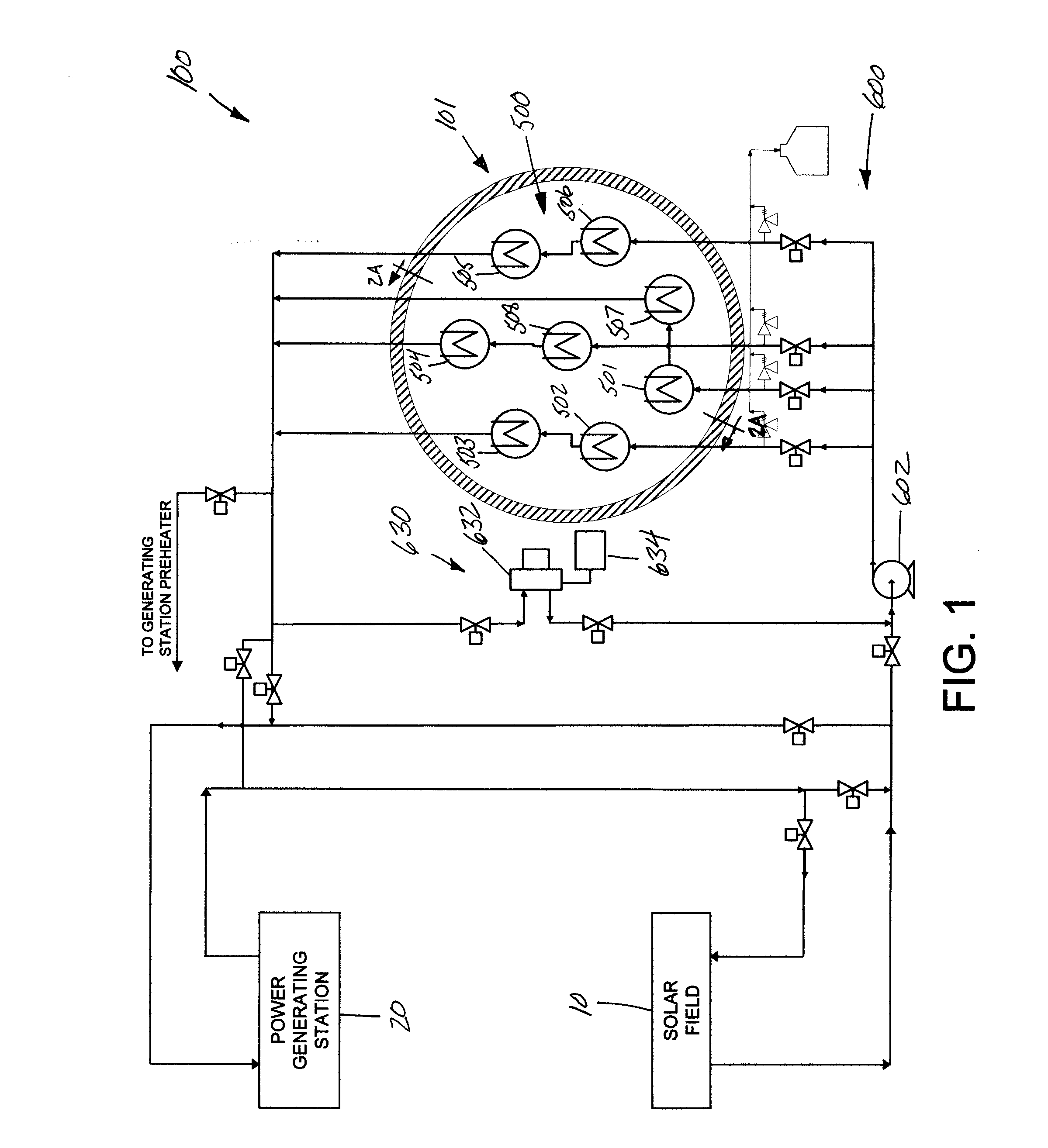
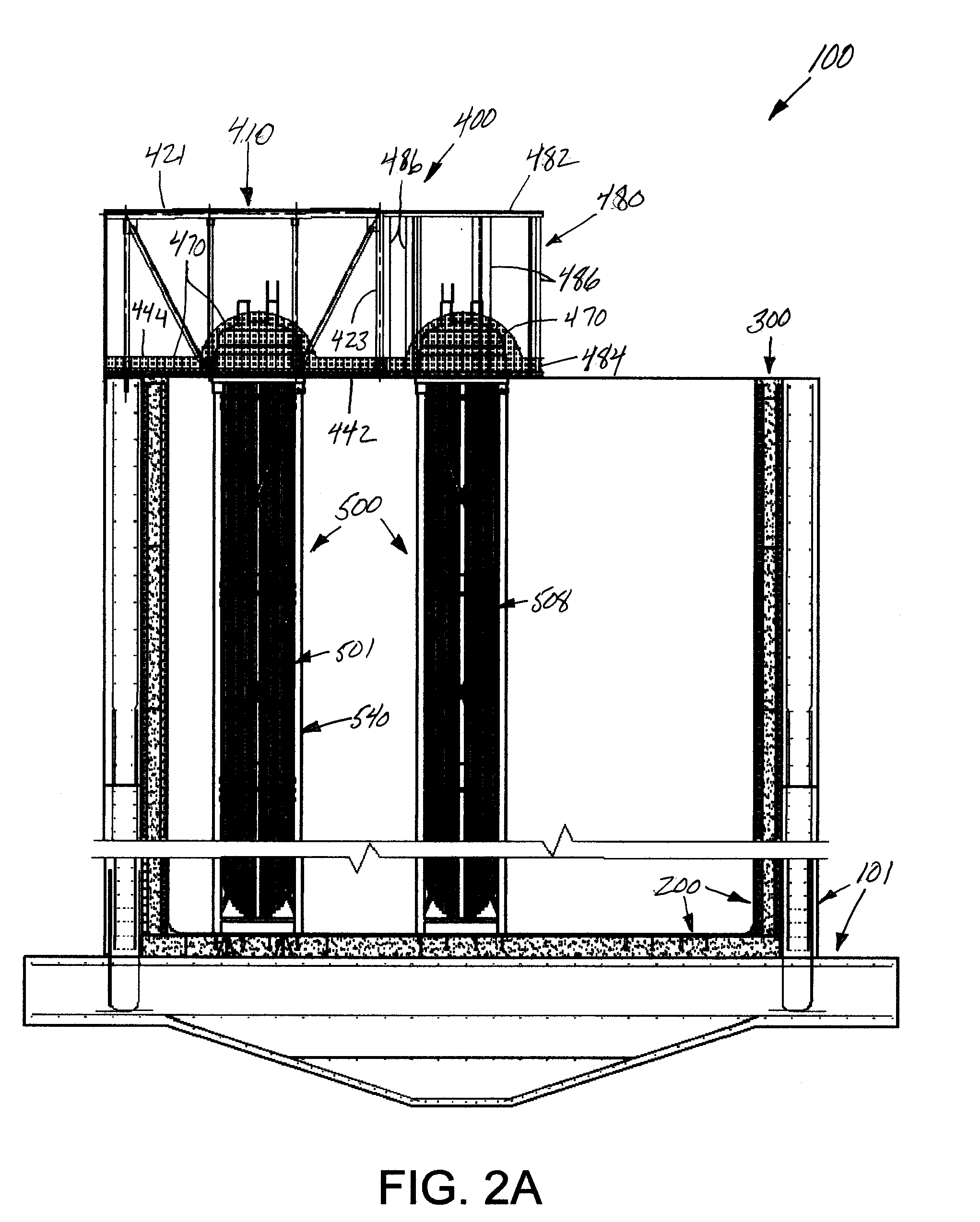
[0062]FIG. 1 is a schematic illustration of a thermal storage system and method in accordance with the present disclosure. The thermal energy storage system 100 is comprised of a containment vessel 101, which contains a heat exchanger or an array 500 of heat exchangers immersed in a molten salt. The system 100 is further comprised of a liquid transfer unit 600 (that may be of a modular design), which circulates a heat transfer fluid through the heat exchangers during operation of the system 100. The liquid transfer unit 600 is comprised of liquid piping, various switching and control valves, a pump 602, and a pressure relief tank 604. The liquid transfer unit 600 may further include a heater loop 630 comprising an oil heater 632 and an expansion tank 634 for heating and circulating heat trans...


PUM

PropertyMeasurementUnit
temperatureaaaaaaaaaa
temperaturesaaaaaaaaaa

Abstract

A containment vessel for a thermal energy storage system comprising a bottom wall joined to a surrounding containment side wall, and a liner comprising a liner bottom disposed upon the bottom wall of the vessel, the liner bottom having an outer perimeter and comprising an array of plates, each of the plates joined at a portion of its perimeter to a portion of the perimeter of an adjacent plate by a flexible joint; and a liner side wall joined to the outer perimeter of the liner bottom and disposed within the containment side wall. A thermal energy storage system comprising the containment vessel and an array of heat exchangers is also disclosed. The heat exchangers are disposed in the vessel, and are each supported by a support frame joined to one of the plates of the array of plates of the liner.

Description

CROSS-REFERENCE TO RELATED PATENT APPLICATIONS[0001]This application claims priority from U.S. provisional patent application Ser. No. 61 / 228,351, filed Jul. 24, 2009, the disclosure of which is incorporated herein by reference. This application is also related to copending commonly owned U.S. patent application Ser. No. 12 / 033,604 of Geiken et al., filed Feb. 19, 2008; and to U.S. patent application Ser. No. 12 / 172,673 of Flynn et al., filed Jul. 14, 2008. The disclosures of these United States patent applications are incorporated herein by reference.BACKGROUND[0002]1. Field of the Invention[0003]The inventions disclosed herein relate generally to energy storage and, more particularly, to thermal energy storage systems and methods thereof.[0004]2. Description of Related Art[0005]Worldwide, there are ever-growing demands for electricity due to increasing populations, technology advancements requiring the use of electricity, and the proliferation of such technology to more and more c...

Claims


Application Information

Patent Timeline
Patent Type & Authority Applications(United States)
IPC IPC(8): F24H7/00B21D51/18
CPCF24D11/003F24H1/181F24H1/208F28D20/00F28D20/021F28D2020/0047Y10T29/49394Y02E60/142Y02E60/145F28F2270/00B21D53/02F28D17/02Y10T29/4935Y02B10/20F28F2265/14Y02E60/14
Inventor BELL, JOHN P.BELL, JOSEPH M.BOWER, MICHAEL S.WALTER, GERARD C.
Owner BELL INDEPENDENT POWER CORP
Why Eureka
Try Eureka