
Hydrocarbon recovery method

a technology of hydrocarbon recovery and hydrocarbon injection, which is applied in the direction of fluid removal, insulation, borehole/well accessories, etc., can solve the problems of increasing the cost associated with gravity-assisted hydrocarbon recovery and relatively slow hydrocarbon recovery, so as to increase the efficiency of hydrocarbon recovery, and reduce the overall need for fluid injection

Inactive Publication Date: 2011-01-27
CONOCOPHILLIPS CO
View PDF30 Cites 13 Cited by
  • Summary
  • Abstract
  • Description
  • Claims
  • Application Information

AI Technical Summary

Benefits of technology

[0007]The disclosure provided herein describes a method for recovering viscous hydrocarbons from an underground formation that increases the efficiency of hydrocarbon recovery while decreasing the overall need for fluid for injection. In certain embodiments, the hydrocarbon recovery process described herein requires far less makeup water for steam generation than methods that do not produce the in-situ water and recover the injectant for recycling. This method provides a cost savings in areas where water resources are limited and / or expensive. Thus, the resources required for hydrocarbon recovery are minimized, as well as the resultant environmental impact.

Problems solved by technology

Since gravity is only drive force behind the SAGD process, hydrocarbon recovery is relatively slow due to slow lateral growth of the heat chamber.
In certain geographic areas, the cost associated with gravity-assisted hydrocarbon recovery is increased due to a lack of water for steam generation, or increased cost of the fluid used for injection.

Method used


Image

  • Hydrocarbon recovery method
  • Hydrocarbon recovery method
  • Hydrocarbon recovery method

Examples


Embodiment Construction

[0018]In some embodiments, the hydrocarbons that are recovered using the methods disclosed herein, may be fluids, such as heavy oils or bitumen, with initial API gravity less than 22°, less than 16°, or less than 10°.

[0019]For some embodiments, any displacement fluid forms the injectant, which may be a gas such as nitrogen, carbon dioxide, methane, or mixtures thereof. Such displacement fluids may also include steam, water, or an organic solvent for use in facilitating hydrocarbon recovery. In certain embodiments where the injectant comprises steam, the injector well couples to a steam source (or steam generator) that supplies the steam at a pressure in a range of about 100-1600 psi. Injectant is introduced into the injector well, then exits the injector well and enters the formation. The well completion may be open hole, or contain slotted or perforated liner wall sections that enable outflow of the steam along the injector portion of the well. The injectant passes into the reservo...


PUM


Abstract

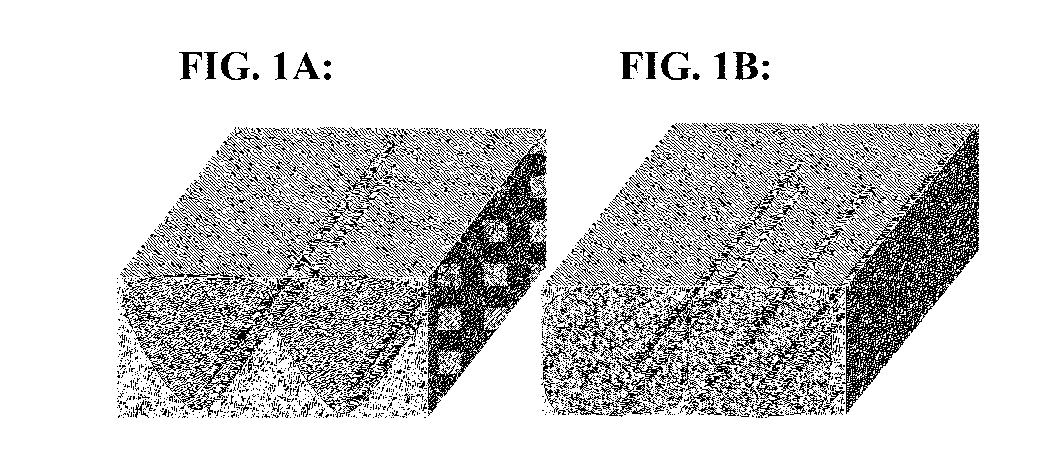
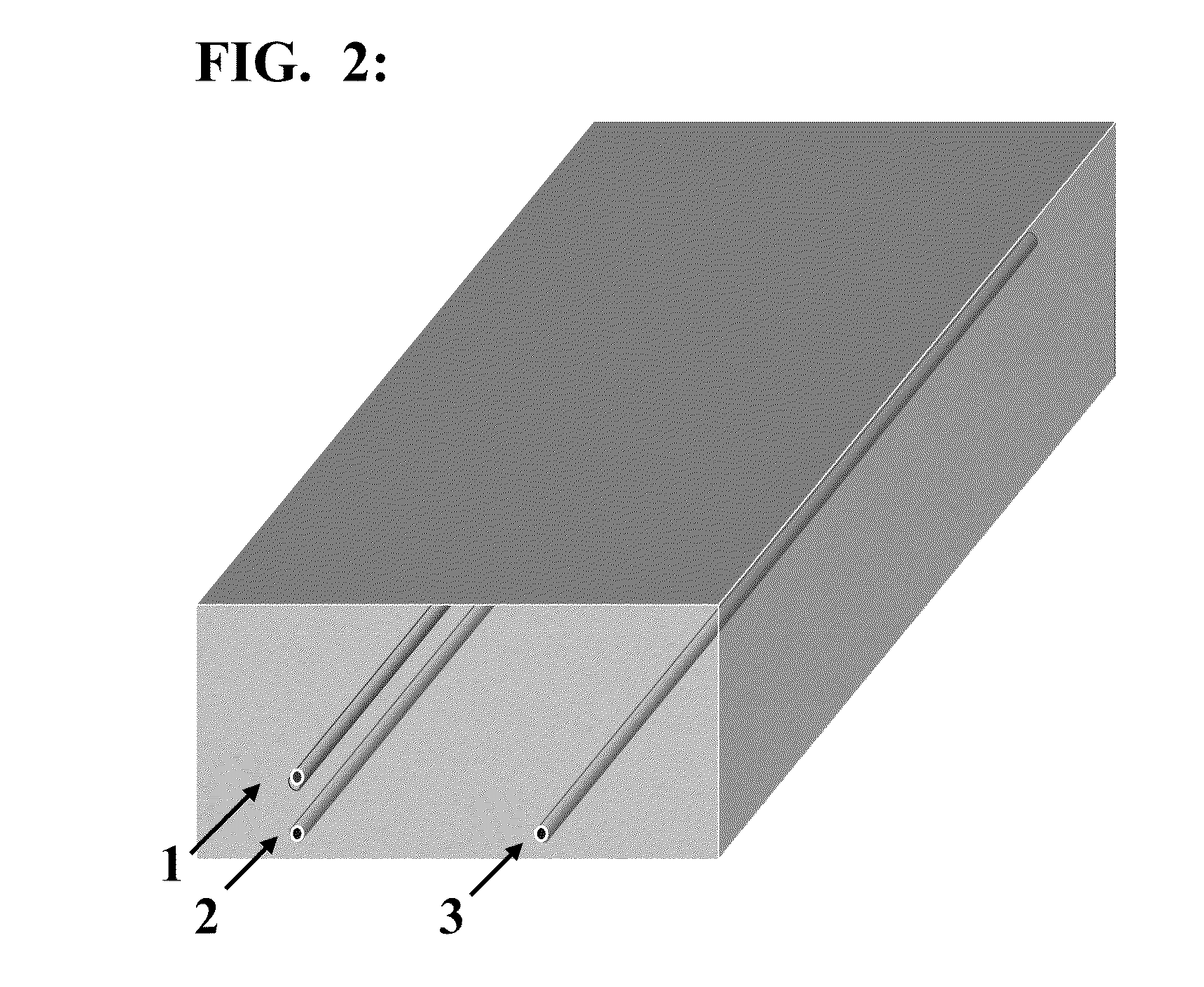
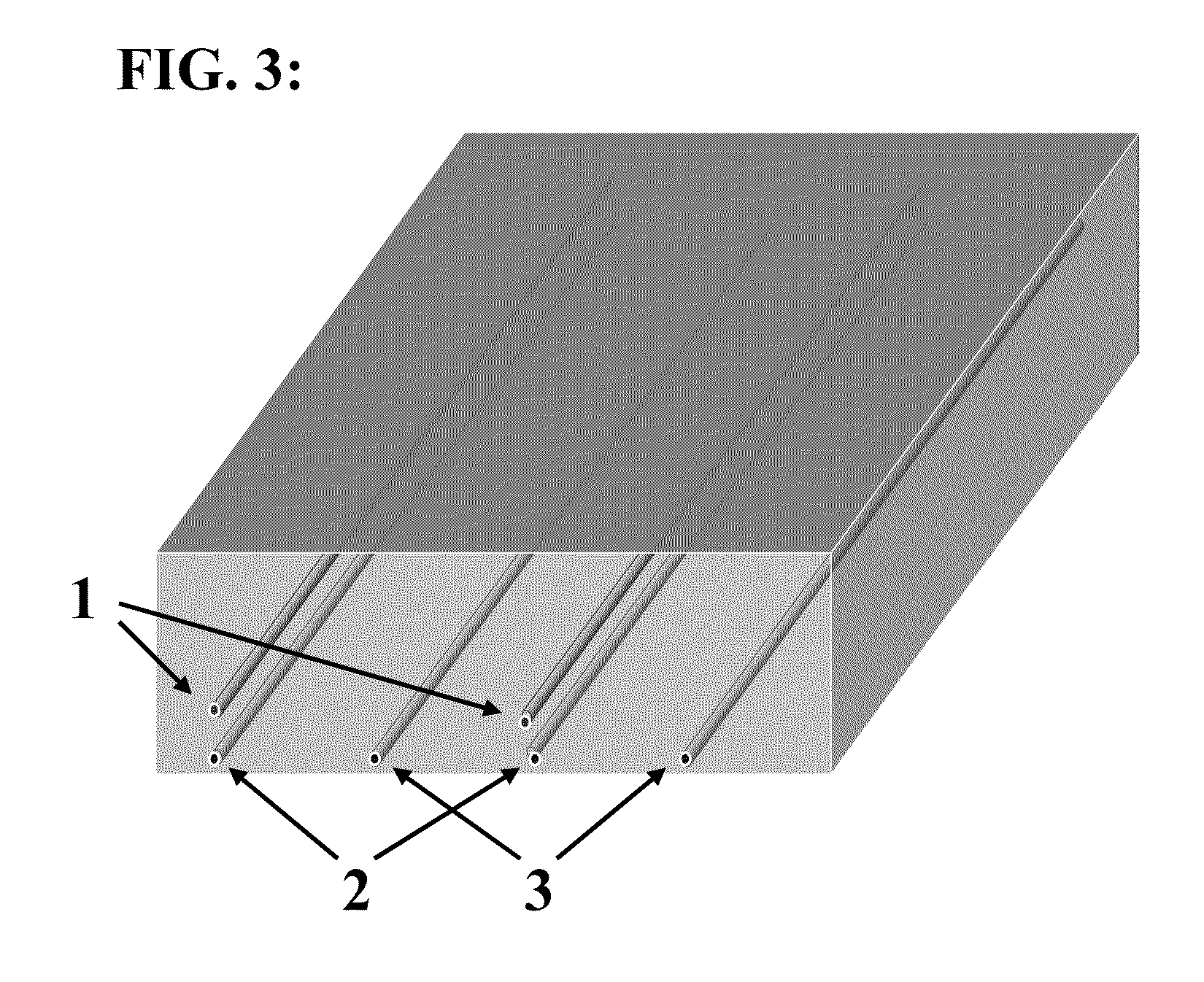
A process for increasing the efficiency of hydrocarbon recovery from an underground formation containing viscous hydrocarbons through the use of both gravity drainage and mobile water drive. The process comprises a pair of vertically-spaced horizontal wells and a laterally offset horizontal well. A heated fluid is injected into the formation via a first well pair, and an adjacent horizontal well creates a pressure sink to draw the heated fluid laterally to assist growth of the formation drainage area for hydrocarbon recovery improvement. Injected fluids recovered from both producers are collected for recycling.

Description

STATEMENT REGARDING FEDERALLY-SPONSORED RESEARCH OR DEVELOPMENT[0001]None.FIELD OF THE DISCLOSURE[0002]The invention generally relates to improved processes for the recovery of viscous hydrocarbons from underground formations, and drive mechanism recovery processes that increase the efficiency and decrease the cost associated with recovering viscous hydrocarbons from a subterranean formation.BACKGROUND OF THE DISCLOSURE[0003]For some time, processes have been employed to heat underground formations containing viscous hydrocarbon deposits, thereby lowering the viscosity of the petroleum contained within and providing a driving force to assist in the recovery of these viscous hydrocarbons. The use of horizontal drilling technology for viscous hydrocarbon recovery is well-established. An large area of contact between the wellbore and the formation can be achieved by drilling wells with a substantially horizontal component (typically, 300 to 2,000 meters). This large contact area allows...

Claims


Application Information

Patent Timeline
IPC IPC(8): E21B43/24
CPCE21B43/305E21B43/2406
Inventor DUONG, ANH NGOC
Owner CONOCOPHILLIPS CO
Learn More