Automatic parking brake having a slip controller

US20110017554A1Active Publication Date: 2011-01-27ROBERT BOSCH GMBH

Image

  • Automatic parking brake having a slip controller
  • Automatic parking brake having a slip controller
  • Automatic parking brake having a slip controller

Examples


Embodiment Construction

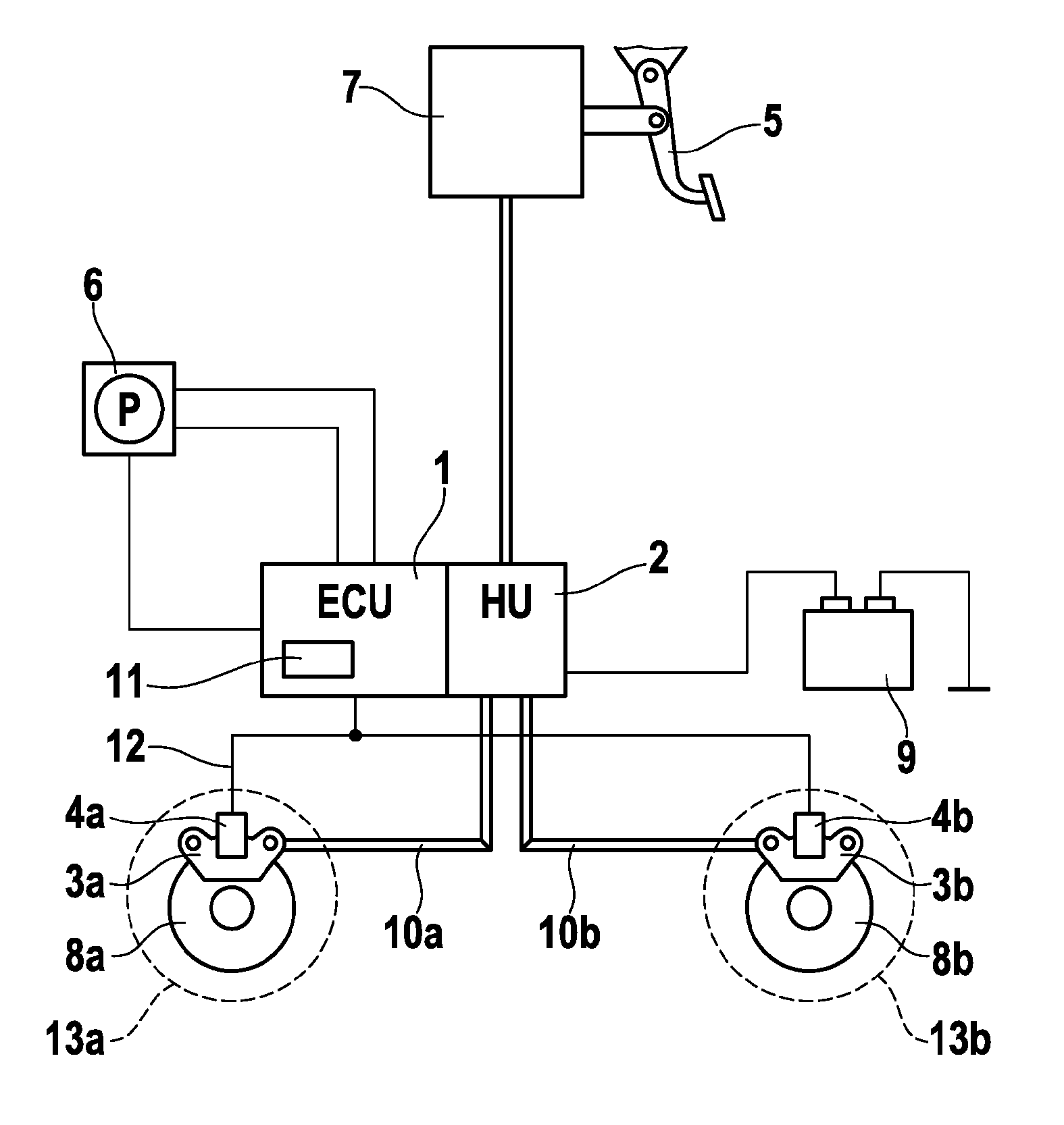
[0016]FIG. 1 shows a block diagram of a hydraulic braking system having an automatic parking brake according to an embodiment of the present invention. In an available manner, the braking system includes a foot brake pedal 5, which acts together with a main brake cylinder via a brake booster (combined in block 7). The brake pressure produced by the driver and amplified is conducted via a hydraulic unit 2, which is designed to perform a slip control, and brake lines 10a, 10b to wheel brakes 3, 8. Wheel brakes 3, 8 are implemented in this example embodiment as disk brakes, which respectively include a brake caliper 3 and a brake disk 8.

[0017]The automatic parking brake includes an operating element 6 (e.g. a push-button switch) for activating and deactivating the parking brake, a control unit 1, connected to push-button switch 6, in which a parking brake algorithm having a slip controller 11 is stored, and multiple electric motors 4a, 4b, which are respectively mounted on a brake cali...


PUM


Abstract

The invention relates to an automatic parking brake for motor vehicles having a plurality of brake actuators (4a, 4b) and an operating element (6) for actuating the parking brake, the braking actuators (4a, 4b) being connected to a controller (1, 11) performing individual wheel slip control upon occurrence of a critical driving situation. Simultaneous locking and thus the loss of lateral force can be prevented if the controller (1, 11) is designed such that the wheel slippage (A2) of a second wheel (13b) is considered when controlling the slippage of a first wheel (13a).

Description

FIELD OF INVENTION[0001]The present invention relates to an automatic parking brake for motor vehicles, a method for controlling slip, and a control unit having a slip controller.BACKGROUND INFORMATION[0002]Automatic parking brakes (APB) typically include an operating element such as, e.g., a push-button switch by which the parking brake may be locked or released. When the operating element is actuated, a control unit connected to it recognizes the parking brake command and accordingly controls an actuator such as, e.g., a hydraulic pump or an electric motor in order to build up braking force on the wheels of the vehicle or to release the brake.[0003]The following considers systems in which electric motors (having gear units) are situated directly on the wheel brakes (so-called ā€œmotor on caliperā€). Such parking brake systems are typically designed so that the driver may operate them when the vehicle is at a standstill and while driving. The possibility of an operation while driving ...

Claims


Application Information

Patent Timeline
27 Jan 2011
Publication
US20110017554A1
IPC
B60T8/176; F16D55/22; F16D65/34; F16D65/28
CPC
B60T7/12; B60T8/32; B60T8/17616
Inventors
BAEHRLE-MILLER, FRANK; BLATTERT, DIETER