
Wind turbine blade and wind power generator using the same

a technology of wind turbine blades and generators, applied in the direction of electric generator control, machines/engines, mechanical equipment, etc., can solve the problems of low flexibility of blades disclosed in patent citation 1 and other problems, to achieve the effect of effectively suppressing noise occurring, reducing noise, and inhibiting the formation of new sources of nois

Active Publication Date: 2011-01-27
MITSUBISHI HEAVY IND LTD
View PDF9 Cites 60 Cited by
  • Summary
  • Abstract
  • Description
  • Claims
  • Application Information

AI Technical Summary

Benefits of technology

[0015]In light of the above circumstances, the present invention provides a wind turbine blade having a serrated plate that can be formed irrespective of the overall structure of the blade and that can be attached in the optimum shape to effectively suppress noise occurring at the trailing edge thereof, and also provides a wind power generator using such a wind turbine blade.
[0033]According to the present invention, because the wind turbine blade is formed by bonding the back skin and the front skin and, on the other hand, the serrated plate having the serrated portion on the rear side thereof is formed so as to be attached by bonding the back skin and the front skin, the serrated plate can be attached in the optimum shape to avoid noise, for example, a shape that can suppress formation of a cross flow, thus effectively suppressing noise occurring at the trailing edge.

Problems solved by technology

The blade disclosed in Patent Citation 1 has low flexibility in fabrication because serrations are molded integrally with the overall blade or are fixed to the blade with bolts.
Thus, serrations formed as an extended portion of a blade can themselves disturb the flow and therefore serve as a new source of noise.

Method used


Image

  • Wind turbine blade and wind power generator using the same
  • Wind turbine blade and wind power generator using the same
  • Wind turbine blade and wind power generator using the same

Examples


first embodiment

[0054]A wind power generator 1 according to an embodiment of the present invention will be described below on the basis of the drawings.

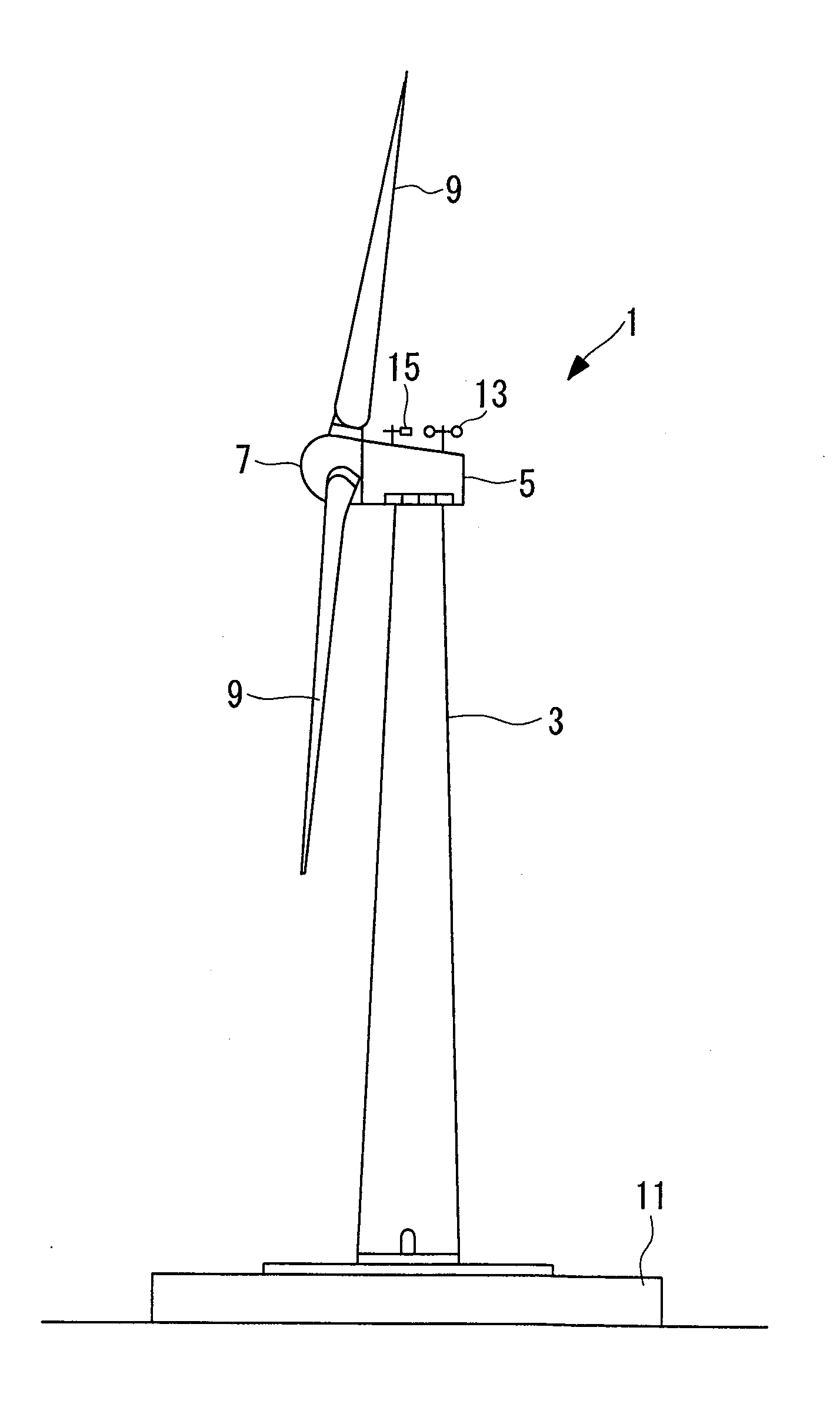
[0055]FIG. 1 is a side view schematically showing the overall structure of the wind power generator 1.

[0056]As shown in FIG. 1, the wind power generator 1 includes a tower 3 provided in an upright position on a foundation 11, a nacelle 5 installed on the top end of the tower 3 so as to be rotatable substantially horizontally, with the tower 3 serving as a pivot, a rotor head 7 provided on the nacelle 5 so as to be rotatable about a substantially horizontal axis, and a plurality of wind turbine blades 9 attached to the rotor head 7 so as to extend radially around the rotation axis thereof and to be rotatable about the blade length direction.

[0057]The force of wind striking the wind turbine blades 9 in the rotation axis direction of the rotor head 7 is converted into power rotating the rotor head 7 about the rotation axis direction thereof.

[0058]An an...

second embodiment

[0089]Next, a second embodiment of the present invention will be described using FIGS. 8 and 9.

[0090]In this embodiment, the basic structure is similar to that of the first embodiment, but it differs in the structure of the trailing edge 33 of the wind turbine blade 9. In this embodiment, therefore, this difference will be described, and a redundant description of the other portions will be omitted.

[0091]The same elements as those of the first embodiment are denoted by the same references, and a detailed description thereof will be omitted.

[0092]FIG. 8 is a partial perspective view showing the attachment structure of the serrated plate 35. FIG. 9 is a partial perspective view showing the joint structure of the back skin 19 and the front skin 21.

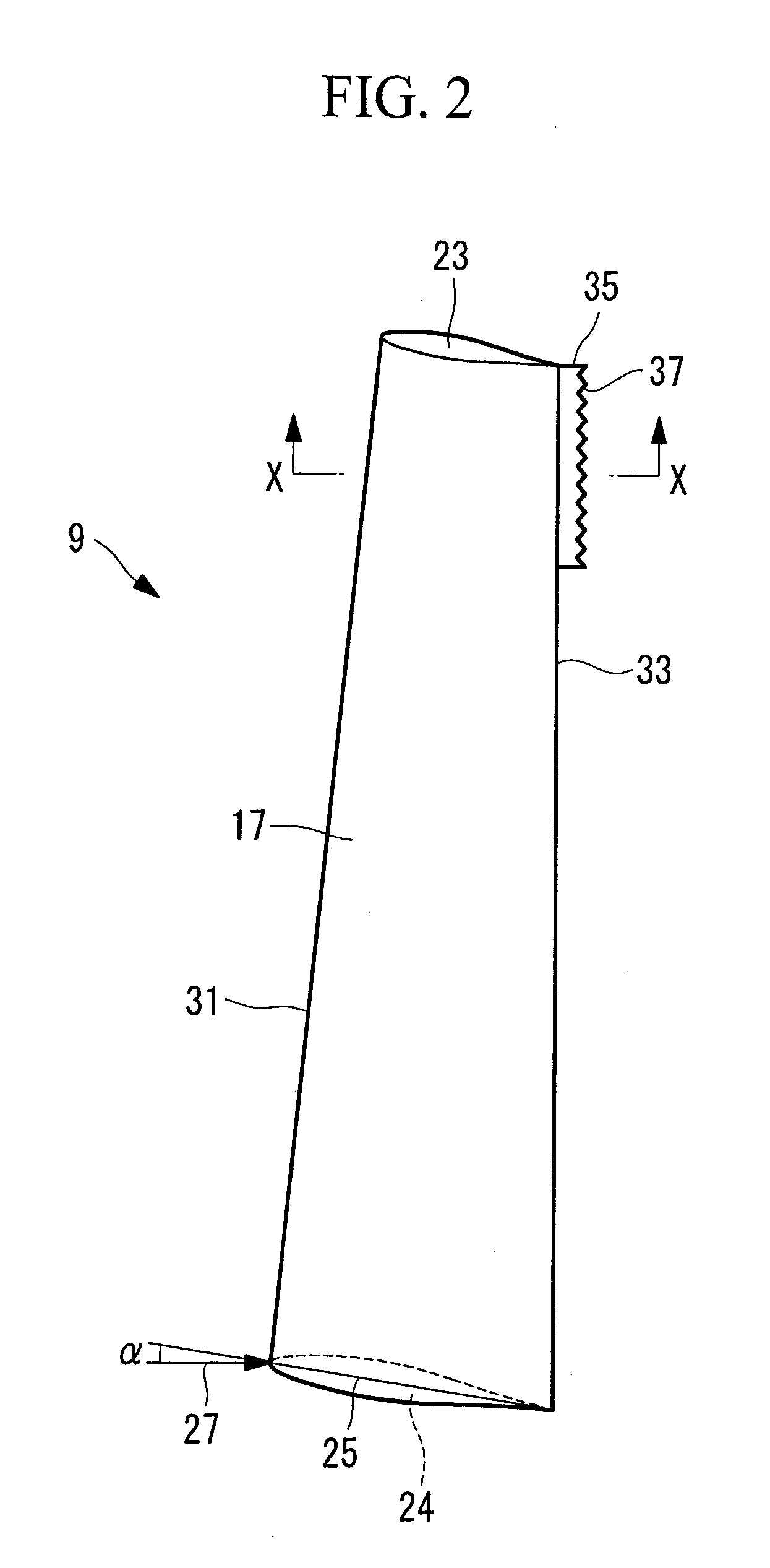
[0093]The serrated plate 35 is formed integrally with the back skin 19 as a trailing-edge extended portion of the back skin 19.

[0094]The serrated plate 35 is angled with respect to the back skin 19 so as to extend along the flow 29 during the...


PUM


Abstract

An object is to provide a wind turbine blade having a serrated plate that can be formed irrespective of the overall structure of the blade, that is attached in the optimum shape, and that can effectively suppress noise occurring at a trailing edge thereof, and also to provide a wind power generator using such a wind turbine blade. Provided is a wind turbine blade (9) formed by bonding a back skin (19) and a front skin (21) and having a serrated plate (35) attached to a trailing edge (33) thereof, and the serrated plate (35) is formed so as to be attached by bonding the back skin (19) and the front skin (21).

Description

TECHNICAL FIELD[0001]The present invention relates to wind turbine blades and wind power generators that generate electricity using such wind turbine blades.BACKGROUND ART[0002]One problem with wind power generators is noise caused by blades. Recently, the size of wind power generators has been increased with the growing demand for high-power wind power generators. Accordingly, the rotor diameter, that is, the length of the wind turbine blades, has increased.[0003]The longer the blades are, the faster the blade tips move. Accordingly, a larger amount of noise occurs, and a further noise reduction has been demanded.[0004]The major sources of noise caused by blades are noise due to vortices at the tips of the blades and noise due to turbulence boundary layers occurring on the surfaces of the blades.[0005]In the related art, to reduce the noise level, it is thought to be effective to reduce the rotational speed of a rotor. That is, if the rotational speed of the rotor is reduced, the f...

Claims


Application Information

Patent Timeline
IPC IPC(8): F03D9/00F01D5/14F03D80/00
CPCF03D1/0608F03D11/00F03D11/0033F05B2240/122Y02E10/722F05B2250/183F05B2260/96Y02E10/721F05B2250/11F03D80/00F03D80/30F03D9/25Y02E10/72F05B2240/3042
Inventor HAYASHI, KENTARONISHINO, HIROSHI
Owner MITSUBISHI HEAVY IND LTD
Features
  • Generate Ideas
  • Intellectual Property
  • Life Sciences
  • Materials
  • Tech Scout
  • Unparalleled Data Quality
  • Higher Quality Content
  • 60% Fewer Hallucinations
Learn More