Feedback circuit and control method for an isolated power converter

a technology of isolated power converters and control methods, which is applied in the direction of dc-dc conversion, power conversion systems, differential amplifiers, etc., can solve the problems of reducing the efficiency of the power converter b>10/b> at light loading, and the power consumption is increased. the effect of light load efficiency of the isolated power converter

Inactive Publication Date: 2011-01-27
RICHTEK TECH
View PDF9 Cites 35 Cited by
  • Summary
  • Abstract
  • Description
  • Claims
  • Application Information

AI Technical Summary

Benefits of technology

[0008]Due to the first and second currents in the opto-coupler decreasing in response to an increase in the output voltage during the light load period, the light load efficiency of the isolated power converter is improved.

Problems solved by technology

However, the increase in the currents Id and Icomp also implies higher power consumption, which lowers the efficiency of the power converter 10 at light loading.

Method used


Image

  • Feedback circuit and control method for an isolated power converter
  • Feedback circuit and control method for an isolated power converter
  • Feedback circuit and control method for an isolated power converter

Examples


Embodiment Construction

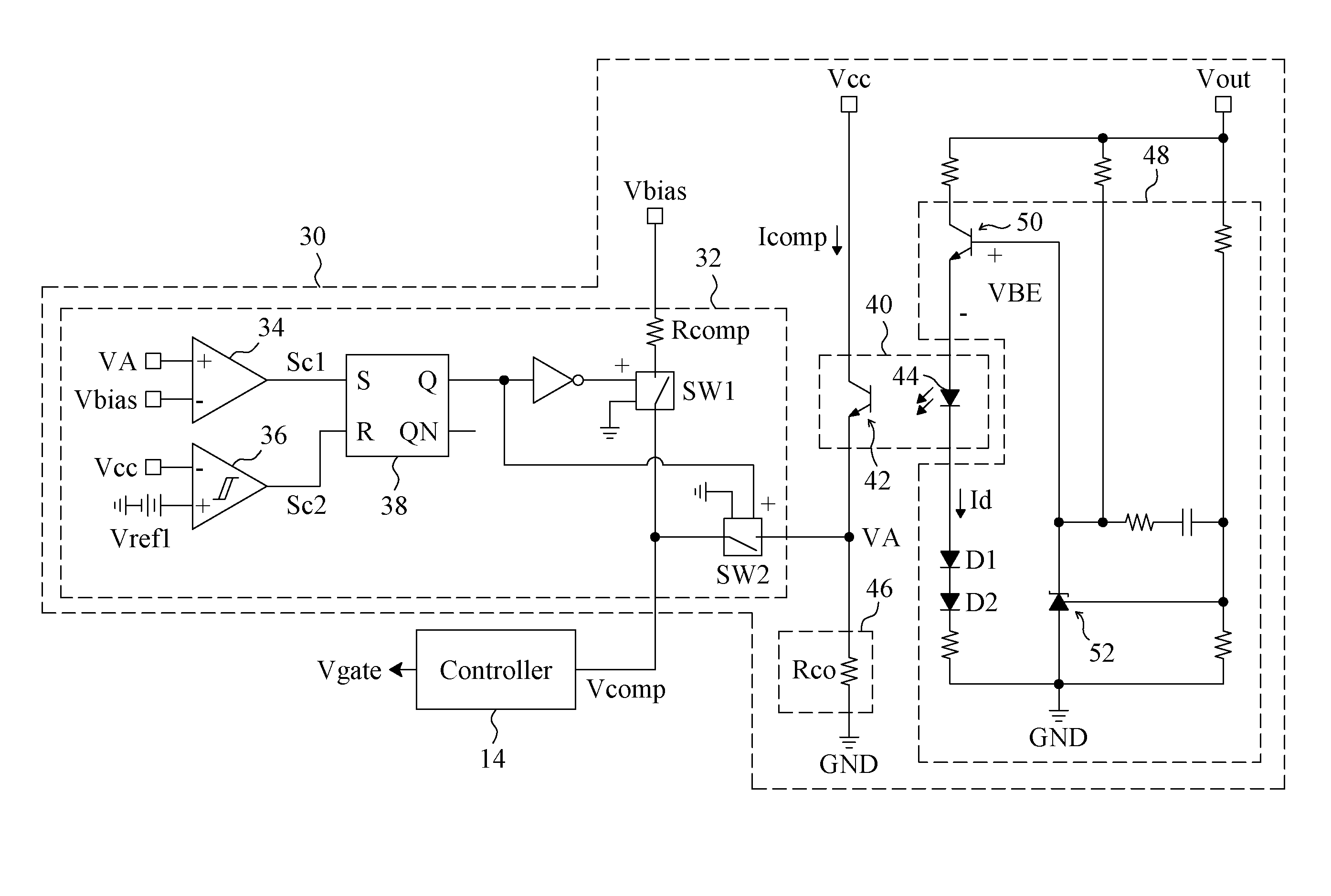
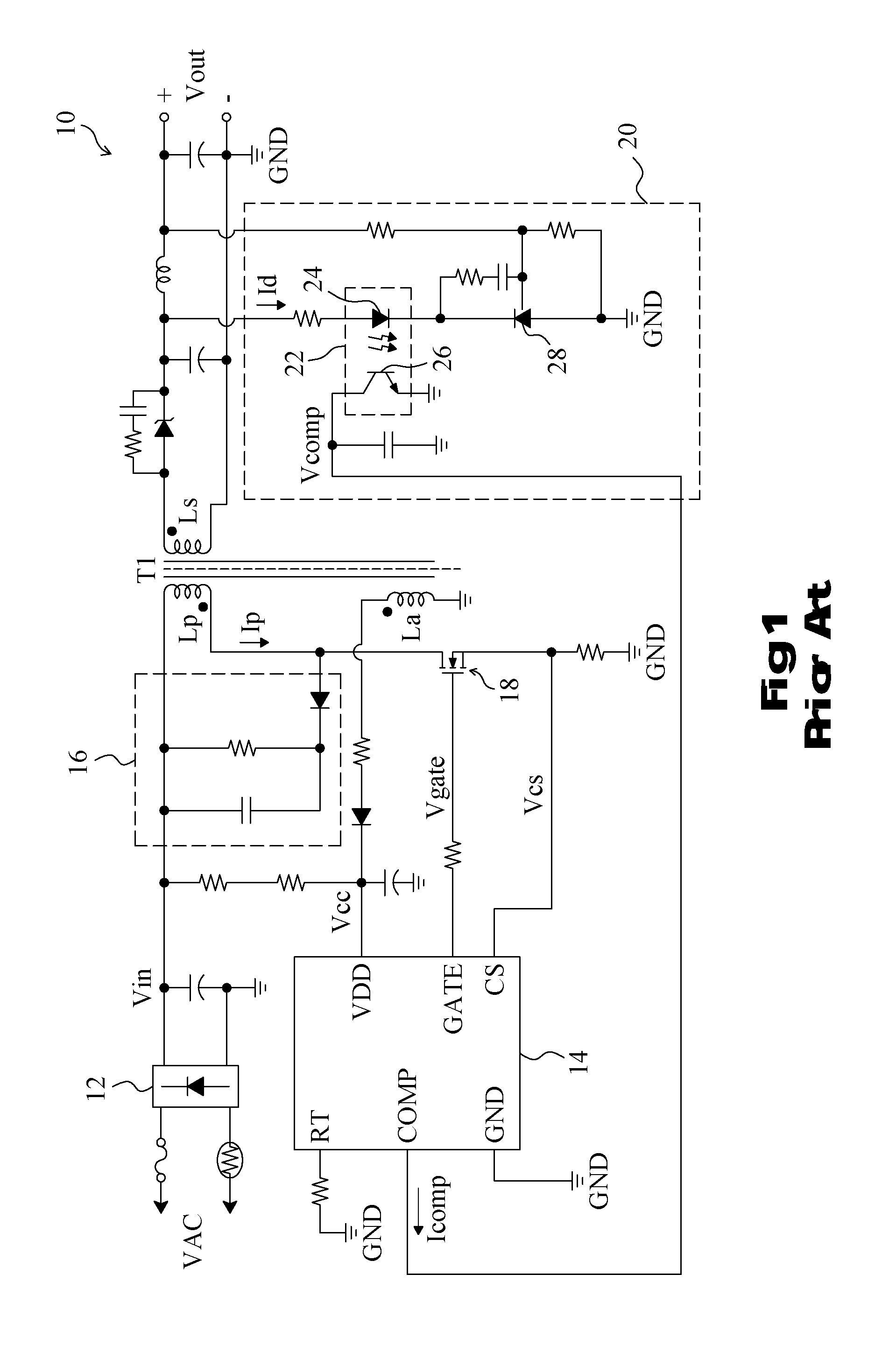
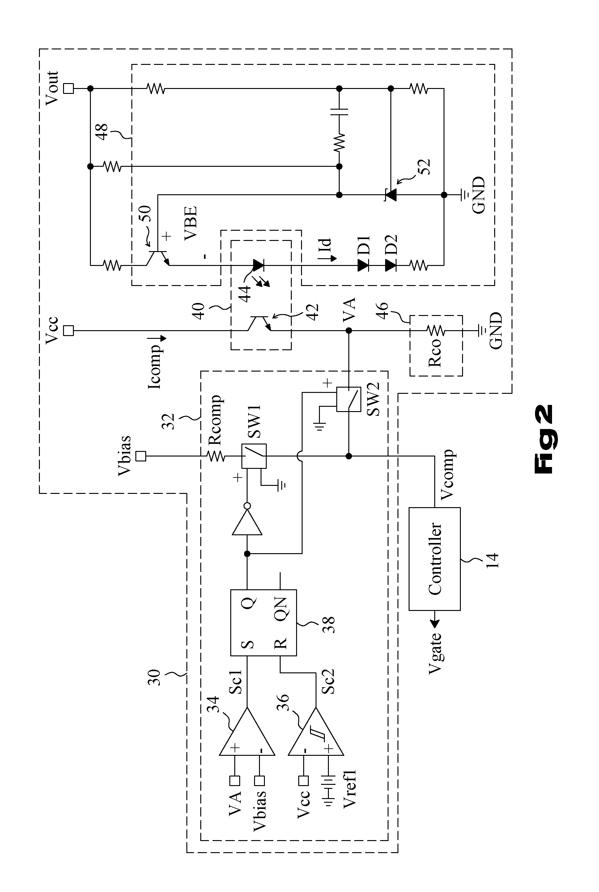
[0013]FIG. 2 is a circuit diagram of a feedback circuit 30 according to the present invention. Referring to FIG. 2 in conjunction with FIG. 1, in the feedback circuit 30, an opto-coupler 40 includes a transistor 42 as an output device of the opto-coupler 40 connected between the power input pin Vcc and a current-to-voltage converter 46, and an LED 44 coupled to the output of the isolated power converter 10, the current Id flowing through the LED 44 and related to the output voltage Vout is amplified by the opto-coupler 40 to produce a current Icomp flowing through the transistor 42, a reversed polarity regulator 48 is connected to the opto-coupler 40 to control the current Id such that the current Id decreases or increases in response to an increase or decrease in the output voltage Vout, respectively, the current-to-voltage converter 46 includes a resistor Rco to generate a voltage VA according to the current Icomp provided by the opto-coupler 40, and a start up circuit 32 operates...


PUM


Abstract

A feedback circuit for an isolated power converter includes an opto-coupler and a reversed polarity regulator. The opto-coupler provides a current related to an output voltage of the isolated power converter. When the isolated power converter enters light load, the output voltage rises and the reversed polarity regulator reduces the current to decrease the power consumption and thus improve the light load efficiency of the isolated power converter.

Description

FIELD OF THE INVENTION[0001]The present invention is related generally to an isolated power converter and, more particularly, to a feedback circuit and control method for an isolated power converter.BACKGROUND OF THE INVENTION[0002]As shown in FIG. 1, a conventional isolated power converter 10 includes a rectifier circuit 12 to convert an alternating-current (AC) voltage VAC to a direct-current (DC) voltage Vin applied to a primary coil Lp of a transformer T1 via a snubber 16, a power switch 18 serially connected to the primary coil Lp, and a controller 14 to generate a control signal Vgate according to a feedback signal Vcomp and a sense signal Vcs proportional to the current Ip flowing through the primary coil Lp, to switch the power switch 18 to convert the voltage Vin to an output voltage Vout. The controller 14 has a power input pin VDD to receive a supply voltage Vcc. A feedback circuit 20 detects the output voltage Vout to generate the feedback signal Vcomp for the controller...

Claims


Application Information

Patent Timeline
Patent Type & Authority Applications(United States)
IPC IPC(8): H02M11/00
CPCH02M3/33523
Inventor TAI, LIANG-PINLIN, TZU-CHENFAN, CHENG-HSUAN
Owner RICHTEK TECH
Why Eureka
Try Eureka